
|
www.riscos.com Technical Support: |
The Sound system provides facilities to synthesise and playback high quality digital samples of sound. Since any sound can be stored digitally, the system can equally well generate music, speech and sound effects. Eight fully independent channels are provided.
The sound samples are synthesised in real time by software. A range of different Voice Generators generate a standard set of samples, to which further ones can be added. The software also includes the facility to build sequences of notes.
The special purpose hardware provided on ARM-based systems simply reads samples at a programmable rate and converts them to an analogue signal. Filters and mixing circuitry on the main board provide both a stereo output (suitable for driving personal hi-fi stereo headphones directly, or connecting to an external hi-fi amplifier) and a monophonic or stereophonic output to the internal speaker(s).
There are four parts to the software for the Sound system: the DMA Handler, the Channel Handler, the Scheduler, and Voice Generators. These are briefly summarised below, and described in depth in later sections.
The DMA Handler manages the DMA buffers used to store samples of sound, and the associated hardware used.
The system uses two buffers of digital samples, stored as signed logarithms. The data from one buffer is read and converted to an analogue signal, while data is simultaneously written to the other buffer by a Voice Generator. The two buffers are then swapped between, so that each buffer is successively written to, then read.
The DMA Handler is activated every time a new buffer of sound samples is required. It sends a Fill Request to the Channel Handler, asking that the correct Voice Generators fill the buffer that has just been read from.
The DMA Handler also provides interfaces to program hardware registers used by the Sound system. The number of channels and the stereo position of each one can be set, the built-in loudspeaker(s) can be enabled or disabled, and the entire Sound system can also be enabled or disabled. The sample length and sampling rate can also be set.
The services of the DMA Handler are mainly provided in firmware requiring privileged supervisor status to program the system devices. It is tightly bound to the Channel Handler, sharing static data space. Consequently, this module must not be replaced or amended independently of the Channel Handler.
The Channel Handler provides interfaces to control the sound produced by each channel, and maintains internal tables necessary for the rest of the Sound system to produce these sounds.
The interfaces can be used to set the overall volume and tuning, to attach the channels to different Voice Generators, and to start sounds with given pitch, amplitude and duration.
The following internal tables are built and maintained: a mapping of voice names to internal voice numbers; a record for each channel of its volume, voice, pitch and timbre; and linear and logarithmic lookup tables for Voice Generators to scale their amplitude to the current overall volume setting.
Fill Requests issued by the DMA Handler are routed through the Channel Handler to the correct Voice Generators. This allows any tables involved to be updated.
The Channel Handler is tightly bound to the DMA Handler, sharing static data space. Consequently, this module must not be replaced or amended independently of the DMA Handler.
The Scheduler is used to queue Sound system SWIs. Its most common use is to play sequences of notes, and a simplified interface is provided for this purpose.
A beat counter is used which is reset every time it reaches the end of a bar. Both its tempo and the number of beats to the bar can be programmed.
You may replace this module, although it is unlikely to be necessary.
Voice Generators generate and output sound samples to the DMA buffer on receiving a Fill Request from the Channel Handler. Typical algorithms that might be used to synthesise a sound sample include calculation, lookup of filtered wavetables, or frequency modulation. A Voice Generator will normally allow multiple channels to be attached.
An interface exists for you to add custom Voice Generators, expanding the range of available sounds. The demands made on processor bandwidth by synthesis algorithms are high, especially for complex sounds, so you must write them with great care.
The DMA Handler manages the hardware used by the Sound system. Two physical buffers in main memory are used. These are accessed using four registers in the sound DMA Address Generator (DAG) within the MEMC (memory controller) chip:
The sound pointer is incremented every time a byte is read by the video controller for output. When it reaches the end of the current buffer the memory controller switches buffers: the sound pointer and buffer end registers are set to the values stored in the next start and next end registers respectively. An interrupt is then issued by IOC (the I/O controller) indicating the buffers have switched, and the DMA handler is entered.
The DMA Handler calls the Channel Handler with a Fill request, asking that the next buffer be filled. (See Channel Handler for details of the Channel Handler.) If this fill is completed, control returns to the DMA Handler and it makes the next start and next end registers point to the buffer just filled. If the fill is not completed then the next registers are not altered, and so the same buffer of sound will be repeated, causing an audible discontinuity.
The rest of this section outlines the factors that you must consider if you choose to reconfigure the Sound system.
There are corresponding rates for each of the above.
A short buffer period is desirable to minimise the size of the buffer and to give high resolution to the length of notes; a long buffer period is desirable to decrease the frequency and number of interrupts issued to the processor. A period of approximately one centisecond is chosen as a default value, although this can be changed, for example to replay lengthy blocks of sampled speech from a disc.
A high sample rate will give the best sound quality. If too high a rate is sought then DMA request conflicts will occur, especially when high bandwidths are also required from VIDC (the Video Controller) by high resolution screen modes. To avoid such contention the output period must not be less than 4![[MU]](../symbols/entities/956.png) S. OUTPUTTING A BYTE TO ONE OF EIGHT CHANNELS EVERY 4S RESULTS IN A SAMPLE PERIOD OF 32s, which gives a maximum sample rate of 31.25kHz.
S. OUTPUTTING A BYTE TO ONE OF EIGHT CHANNELS EVERY 4S RESULTS IN A SAMPLE PERIOD OF 32s, which gives a maximum sample rate of 31.25kHz.
The clock for the Sound system is derived from the system clock for the video controller, which is then divided by a multiple of 24. Current ARM based computers use a VIDC system clock of 24MHz, 25.175MHz or 36MHz, depending on the screen mode and monitor type selected. The default output period is 6S_ WHICH IS COMPATIBLE WITH VIDC SYSTEM CLOCKS RUNNING AT MULTIPLES OF 4MHZ FROM 12MHZ UPWARDS (IE 12MHZ_ 16MHZ_ 20MHZ...). THIS 6s output period is obtained as follows from the 24MHz and 36MHz VIDC system clocks:
Unfortunately with a VIDC system clock of 25.175MHz (used for VGA screen modes) the same output period cannot be produced. The divider used is the same as for a 24MHz VIDC system clock (ie 144, or 6 × 24), which results in a slightly shorter output period, and so sounds are approximately a semitone higher.
Outputting a byte to one of eight channels every 6S RESULTS IN A SAMPLE PERIOD OF 48s, which gives a default sample rate of 20.833kHz.
The DMA buffer length depends on the number of channels, the sample rate, and the buffer period. It must also be a multiple of 4 words. Using the defaults outlined above, the lengths shown in the middle two columns of the following table are the closest alternatives:
Buffer lengths for one centisecond sample, at sample rate of 20.833 kHz:
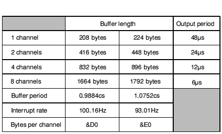
The system default buffer period is chosen as 0.9984 centiseconds, thus the sample length is 208 bytes, or 52 words (13 DMA quad-word cycles). The buffer length is a multiple of this, depending on how many channels are used.
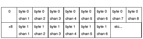
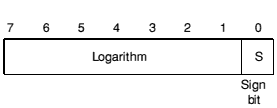
The sound DMA system systematically outputs bytes at the programmed sample rate; each (16-byte) load of DMA data from memory is synchronised to the first stereo image position. Each byte must be stored as an eight bit signed logarithm, ready for direct output to the VIDC chip:
Multiple channel operation is possible with two, four or eight channels; in this case the data bytes for each channel must be interleaved throughout the DMA buffer at two, four or eight byte intervals. When output the channels are multiplexed into what is effectively one half, one quarter or one eighth of the sample period, so the signal level per channel is scaled down by the same amount. Thus the signal level per channel is scaled, depending on the number of channels; but the overall signal level remains the same for all multi-channel modes.
Showing the interleaving schematically:
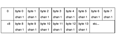
Output rate = 20 kHz
Image registers 0 - 7 programmed identically
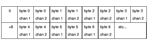
Output rate = 40 kHz
Image registers 0+2+4+8 and 1+3+5+7 programmed per channel
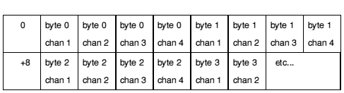
Output rate = 80 kHz
Image registers 0+4, 1+5, 2+6 and 3+7 programmed per channel
Output rate = 160 kHz
Image registers programmed individually.
The Channel Handler manages the interleaving for you by passing the correct start address and increment to the Voice Generator attached to each channel.
The Channel Handler registers itself with the DMA Handler by passing its address using Sound_Configure. At this address there must be a standard header:
| Offset | Value |
|---|---|
| 0 | pointer to fill code |
| 4 | pointer to overrun fixup code |
| 8 | pointer to linear-to-log table |
| 12 | pointer to log-scale table |
The fill code handles fill requests from the DMA Handler. The Channel Handler translates the fill request to a series of calls to the Voice Generators, passing the required buffer offsets so that data from all channels correctly interleaves. Any unused channels within the buffer are set to zero by the Channel Handler so they are silent.
The overrun fixup code deals with channels that are not successfully filled within a single buffer period and hence repeat the same DMA buffer. This feature is no longer supported in RISC OS and the fixup code is never called. (In the Arthur OS the offending channel was marked as overrun, the previous Channel Handler was aborted, and a new buffer fill initiated.)
The pointer to the linear-to-log table holds the address of the base of an 8 Kbyte table which maps 32-bit signed integers directly to 8-bit signed volume-scaled logarithms in a suitable format for output to the VIDC chip.
The pointer to the log-scale table holds the address of a 256-byte table which scales the amplitude of VIDC-format 8-bit signed logarithms from their maximum range down to a value scaled to the volume setting. Voice Generators should use this table to adjust their overall volume.
The Channel Handler maintains a 256 byte Sound Channel Control Block (SCCB) for each channel. An SCCB contains parameters and flags used by Voice Generators, and an extension area for programmers to pass any essential further data. Such an extension must be well documented, and used with care, as it will lead to Voice Generators that are no longer wholly compatible with each other.
The 9 initial words hold values that are normally stored in R0 - R8 inclusive. They are loaded from the SCCB using the instruction LDMIA R9,{R0-R8}
| Offset | Value |
|---|---|
| 0 | gate bit + channel amplitude (7-bit log) |
| 1 | index to voice table |
| 2 | instance number for attached voice |
| 3 | control/status bit flags |
| 4 | phase accumulator pitch oscillator |
| 8 | phase accumulator timbre oscillator |
| 12 | number of buffer fills left to do (counter) |
| 16 | (normally working R4) |
| 20 | (normally working R5) |
| 24 | (normally working R6) |
| 28 | (normally working R7) |
| 32 | (normally working R8) |
| 36 - 63 | reserved for use by Acorn (28 bytes) |
| 64 - 255 | available for users |
The flag byte indicates the state of the voice attached to the channel, and may be used for allocating voices in a polyphonic manner. Each time a Voice Generator completes a buffer fill and returns to the Channel Handler it returns an updated value for the Flags field in R0.
It is the responsibility of the Channel Handler to store the returned flag byte, and to update the other fields of each SCCB as necessary.
Note - In the Arthur OS, the flag byte was also used to detect channels that had overrun. If any were found then a call was made indirected through the fix up pointer (see above).
The Channel Handler uses a voice table recording the names of voices installed in the 32 available voice slots. It is always accessed through the SWI calls provided, and so its format is not defined.
The Scheduler registers itself with the DMA Handler by passing its address using Sound_Configure. At this address there must be a pointer to the code for the Scheduler.
Although the Scheduler is principally designed for queuing sound commands it can be used to issue other SWIs. Thus it could be used to control, for example, an external instrument interface (such as a Musical Instrument Digital Interface (MIDI) expansion podule), or a screen-based music editor with real-time score replay.
Extreme care must be used with the Scheduler, as it has limitations. R2 - R7 are always cleared when the SWI is issued, and the error-returning form ('X' form) of the SWI is forced. Return parameters are discarded. If pointers are to be passed in R0 or R1 then the data they address must be preserved until the SWI is called. If a SWI will not work within these limitations it must not be called by the Scheduler.
The Scheduler implements the queue as a circular chain of records. A stack listing the free slots is also kept. The number of free slots varies not only according to how many events are queued, but also to how the events are 'clustered'.
The queue is always accessed through the SWI calls provided, and so its precise format is not defined.
Every centisecond the beat counter is advanced according to the tempo value, and any events that fall within the period are activated in strict queuing order. Voice and parameter change events are processed and the SCCB for each Voice Generator updated as necessary by the Channel Handler, before fill requests are issued to the relevant Voice Generators.
A Voice Generator is added to the Sound system by issuing a Sound_InstallVoice call, which passes its address to the Channel Handler. At this address there must be a standard header:
| Offset | Contents |
|---|---|
| 0 | B FillCode |
| 4 | B UpdateCode |
| 8 | B GateOnCode |
| 12 | B GateOffCode |
| 16 | B Instantiate |
| 20 | B Free |
| 24 | LDMFD R13!,{pc} |
| 28 | Offset from start of header to voice name |
The Fill, Update, GateOn and GateOff entries provide services to fill the DMA buffer at different stages of a note, as detailed in the Entry points for buffer filling.
The Instantiate and Free entries provide facilities to attach or detach the Voice Generator to or from a channel, as detailed in the Voice instantiation.
The Install entry was originally to be called when a Voice Generator was initialised. Since Voice Generators are now implemented as Relocatable Modules, which offer exactly this service in the form of the Initialisation entry point, this field is not supported and simply returns to the caller (LDMFD R13!,{pc} above).
The voice name is used by the Channel Handler voice table. It should be both concise and descriptive. The offset must be positive relative - that is, the voice name must be after the header.
A fill request to a Voice Generator is made by the Channel Handler using one of the four buffer fill entry points. The registers are allocated as follows:
Further parameters are available in the SCCB for that channel, which is addressed by R9. See the chapter entitled Channel Handler for details. The usage of the parameters depends on which of the four entry points is called.
The ARM is in IRQ mode with interrupts enabled.
The routine must fill the buffer with 8 bit signed logarithms in the correct format for direct output to the VIDC chip:
The ARM is in IRQ mode with interrupts enabled. They must remain enabled to ensure that system devices do not have a lengthy wait to be serviced. The code for a Voice Generator must therefore be re-entrant, and R14 must not be used as a subroutine link register, since an interrupt will corrupt it. Sufficient IRQ stack depth must be maintained for system IRQ handling. You can enter SVC mode if you wish.
When a Voice Generator has completed a buffer fill it sets a flag byte in R0, and returns to the Channel Handler using LDMFD R13!,{PC}. The flag byte shows the status of each channel, and is used to prioritise fill requests to the Voice Generators.
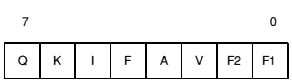
| Bit | Meaning |
|---|---|
| Q | Quiet (GateOff flag) |
| K | Kill pending (GateOn flag) |
| I | Initialise pending (Update flag) |
| F | Fill pending |
| A | Active (normal Fill in progress) |
| V | oVerrun flag (no longer supported) |
| F2, F1 | 2-bit Flush pending counter |
There are four different entry points for buffer filling, which are used at the different stages of a note. It is the responsibility of the Channel Handler to determine which Voice Generator to call, which entry should be used, and to update the SCCB as necessary when these calls return.
The GateOn entry is used whenever a sound command is issued that requires a new envelope. Normally any previous synthesis is aborted and the algorithm restarted.
On exit a the A bit (bit 3) of the flag byte is set.
The Update entry is used whenever a sound command is issued that requires a smooth change, without a new envelope (using extended amplitudes &180 to &1FF in the *Sound command for example). Normally the previous algorithm is continued, with only the amplitude, pitch and duration parameters supplied by the SCCB updated.
On exit the A bit (bit 3) of the flag byte is returned unless the voice is to stop sounding; for example if the envelope has decayed to zero amplitude. In these cases the F2 bit (bit 1) is set, and the Channel Handler will automatically flush out the next two DMA buffers, before becoming dormant.
The Fill entry is used when the current sound is to continue, and no new command has been issued.
On exit it is normal to return the same flags as for the Update entry.
The GateOff entry is used to finish synthesising a sound. Simple voices may stop immediately, which is liable to cause an audible 'click'; more refined algorithms might gradually release the note over a number of buffer periods. A GateOff entry may be immediately followed by a GateOn entry.
On exit the F2 bit (bit 1) is set if the voice is to stop sounding, or the A bit (bit 3) is set if the voice is still being released.
Two entry points are provided to attach or detach a voice generator and a sound channel. On entry the ARM is in Supervisor mode, and the registers are allocated as follows:
| Register | Function |
|---|---|
| R0 | physical Channel number -1 (0 to 7) |
| R14 | usable |
The return address is on top of the stack. All other registers must be preserved by the routines, which must exit using LDMFD R13!,{pc}
R0 is preserved if the call was successful, else it is altered.
The Instantiate entry is called to inform the Voice Generator of a request to attach a channel to it. Each channel attached is likely to need some private workspace. A Voice Generator should ideally be able to support eight channels. The request can either be accepted (R0 preserved on exit), or rejected (R0 altered on exit).
The usual reason for rejection is that an algorithm is slow and is already filling as many channels as it can within each buffer period: for example very complex algorithms, or ones that read long samples off disc.
The Free entry is called to inform the Voice Generator of a request to detach a channel from it. The call must release the channel and preserve all registers.
R0 =
R1 = &54 (reason code)
R0, R1 preserved
This call is made to signal that a part of the Sound system is about to start up or finish.
R0 = number of channels, rounded up to 1,2,4 or 8
R1 = sample length (in bytes per channel - default 208)
R2 = sample period (in s per channel - default 48)
R3 = pointer to Channel Handler (normally 0 to preserve system Handler)
R4 = pointer to Scheduler (normally 0 to preserve system Scheduler)
R0 - R4 = previous values
Interrupt status is undefined
Fast interrupts are enabled
Processor is in SVC mode
Not defined
This software interrupt is used to configure the number of sound channels, the sample period and the sample length. It can also be used by specialised applications to replace the default Channel Handler and Scheduler.
All current settings may be read by using zero input parameters.
The actual values programmed are subject to the limitations outlined earlier.
None
R0 = new state:
R0 = previous state
Interrupt status is undefined
Fast interrupts are enabled
Processor is in SVC mode
Not defined
This software interrupt is used to enable or disable all Sound interrupts and DMA activity. This guarantees to inhibit all Sound system bandwidth consumption once a successful disable has been completed.
None
R0 = channel (C) to program
R1 = image position:
R0 preserved
R1 = previous image position, or -128 if R0  8 on entry
Interrupt status is undefined
Fast interrupts are enabled
Processor is in SVC mode
Not defined
For N physical channels enabled, this call will program stereo registers C, C+N, C+2N... up to stereo register 8. For example, if two channels are currently in use, and channel 1 is programmed, channels 3, 5 and 7 are also programmed; if channel 3 is programmed, channels 5 and 7 are also programmed, but not channel 1.
This Software call only updates RAM copies of the stereo image registers and the new positions, in fact, take effect on the next sound buffer interrupt.
IRQ code can call this SWI directly for scheduled image movement.
None
R0 = new state:
R0 = previous state
Interrupt status is undefined
Fast interrupts are enabled
Processor is in SVC mode
Not defined
This software interrupt enables/disables the monophonic or stereophonic mixed signal(s) to the internal loudspeaker amplifier(s), if present. It has no effect on the external stereo headphone/amplifier output.
This SWI disables the speaker(s) by muting the signal; you may still be able to hear a very low level of sound.
R0 = sound volume (1 - 127) (0 to inspect last setting)
R0 = previous volume
Interrupt status is undefined
Fast interrupts are enabled
Processor is in SVC mode
Not defined
This call sets the maximum overall volume of the Sound system. A change of 16 in the volume will halve or double the volume. The command scales the internal lookup tables that Voice Generators use to set their volume; some custom Voice Generators may ignore these tables and so will be unaffected.
A large amount of calculation is involved in this apparently trivial call. It should be used sparingly to limit the overall volume; the volume of each channel should then be set individually.
None
Converts a signed integer to a signed logarithm, scaling it by volume
R0 = 32-bit signed integer
R0 = 8-bit signed volume-scaled logarithm
Interrupt status is undefined
Fast interrupts are enabled
Processor is in SVC mode
Not defined
This call maps a 32-bit signed integer to an 8 bit signed logarithm in VIDC format. The result is scaled according to the current volume setting. Table lookup is used for efficiency.
None
R0 = 8-bit signed logarithm
R0 = 8-bit signed volume-scaled logarithm
Interrupt status is undefined
Fast interrupts are enabled
Processor is in SVC mode
Not defined
This software interrupt maps an 8-bit signed logarithm in VIDC format to one scaled according to the current volume setting. Table lookup is used for efficiency.
R0 = pointer to Voice Generator
R1 = voice slot (0 to install in next free slot, else 1 - 32)
R0 = pointer to name of previous voice, or null terminated error string if R1 = 0
R1 = voice number allocated, or 0 if unable to install
Interrupt status is undefined
Fast interrupts are enabled
Processor is in SVC mode
Not defined
This software interrupt is used by Voice Modules or Libraries to add a Voice Generator to the table of available voices. If an error occurs, this SWI does not set V in the usual manner. Instead R1 is zero on exit, and R0 points directly to a null-terminated error string.
If R0 is in the range 0 - 3, this call takes other action as follows:
R0 = 0
R1 = voice slot
R0 = pointer to name of installed voice
R1 preserved
This call reads the name of the voice installed in the specified slot. If the slot is unused RISC OS gives a null pointer. (The Arthur OS gave a pointer to the string '*** No Voice'.)
Adds a voice to the Sound system, specifying its name in the local language
R0 = 1
R1 = voice slot (0 to install in next free slot, else 1 - 32)
R2 = pointer to Voice Generator
R3 = pointer to voice name in local language, or 0 if no local name
R0 preserved
R1 = voice number allocated, or 0 if unable to install
R2 = pointer to name of previous voice, or null terminated error string if R1 = 0
R3 preserved
This software interrupt is used by Voice Modules or Libraries to add a Voice Generator to the table of available voices, specifying its name in the local language. If an error occurs, this SWI does not set V in the usual manner. Instead R1 is zero on exit, and R0 points directly to a null-terminated error string.
This reason code is not available in RISC OS 2.
Reads the name of the voice installed in the specified slot, and its local name
R0 = 2
R1 = voice slot
R0, R1 preserved
R2 = pointer to name of installed voice
R3 = pointer to name of installed voice in local language
This call reads the name of the voice installed in the specified slot, and its local name. If the slot is unused RISC OS gives a null pointer. (The Arthur OS gave a pointer to the string '*** No Voice'.) The local name is otherwise guaranteed to be non-null and valid.
This reason code is not available in RISC OS 2.
Changes the local name of the voice installed in the specified slot
R0 = 3
R1 = voice slot
R2 = 0
R3 = pointer to new voice name in local language
R0 - R3 preserved
This call changes the local name of the voice installed in the specified slot. The local name is set to the new name given, even if it had no local name before this call was made.
This reason code is not available in RISC OS 2.
R1 = voice slot to remove (1 - 32)
R0 = pointer to name of previous voice (or error message)
R1 is voice number de-allocated (0 for FAIL)
Interrupt status is undefined
Fast interrupts are enabled
Processor is in SVC mode
Not defined
This software interrupt is used when Voice Modules or Libraries are to be removed from the system. It notifies the Channel Handler that a RAM-resident Voice Generator is being removed. If an error occurs, this SWI does not set V in the usual manner. Instead R1 is zero on exit, and R0 points directly to a null-terminated error string.
This call must also be issued before the Relocatable Module Area is Tidied, since the module contains absolute pointers to Voice Generators that are likely to exist in the RMA.
None
R0 = channel number (1 - 8)
R1 = voice slot to attach (0 to detach and mute channel)
R0 preserved (or 0 if illegal channel number)
R1 = previous voice number (or 0 if not previously attached)
Interrupt status is undefined
Fast interrupts are enabled
Processor is in SVC mode
Not defined
This call attaches a voice with a given slot number to a channel. The previous voice is shut down and the new voice is reset.
Different algorithms have different internal state representations so it is not possible to swap Voice Generators in mid-sound.
None
R0 is AAAACCCC Amp/Channel
R1 is DDDDPPPP Duration/Pitch
R0,R1 preserved
Interrupt status is undefined
Fast interrupts are enabled
Processor is in SVC mode
Not defined
This call is identical to Sound_Control, but the parameters are packed 16-bit at a time into low R0, high R0, low R1, high R1 respectively. It is provided for BBC compatibility and for the use of the Scheduler. The Sound_Control call should be used in preference where possible.
None
R0 = new tuning value (or 0 for no change)
R0 = previous tuning value
Interrupt status is undefined
Fast interrupts are enabled
Processor is in SVC mode
Not defined
This call sets the tuning for the Sound system in units of 1/4096 of an octave.
The command *Tuning 0 may be used to restore the default tuning.
None
None
Converts a pitch to internal format (a phase accumulator value)
R0 = 15-bit pitch value:
R0 = 32-bit phase accumulator value, or preserved if R0 &8000 on entry
Interrupt status is undefined
Fast interrupts are enabled
Processor is in SVC mode
Not defined
This software interrupt maps a 15-bit pitch to an internal format pitch value (suitable for the standard voice phase accumulator oscillator).
None
None
R0 = channel number (1 - 8)
R1 = amplitude:
R0 - R3 preserved
Interrupt status is undefined
Fast interrupts are enabled
Processor is in SVC mode
Not defined
This call allows real-time control of a specified Sound Channel. The parameters are immediately updated and take effect on the next buffer fill.
Gate on and off correspond to the start and end of a note and of its envelope (if implemented). 'Smooth' update occurs when note parameters are changed without restarting the note or its envelope - for example when the pitch is changed to achieve a glissando effect.
If any of the parameters are invalid the call does not generate an error; instead it returns without performing any operation.
R0 = channel number (1 - 8)
R1 = pointer to voice name (ASCII string, null terminated)
R0 is preserved, or 0 for fail
R1 is preserved
Interrupt status is undefined
Fast interrupts are enabled
Processor is in SVC mode
Not defined
This call attaches a named voice to a channel. If no exact match for the name is found then an error is generated and the old voice (if any) remains attached. If a match is found then the previous voice is shut down and the new voice is reset.
Different algorithms have different internal state representations so it is not possible to swap Voice Generators in mid-sound.
None
R0 = channel number (1 - 8)
R1 = offset to read from (0 - 255)
R0 preserved (or 0 if fail, invalid channel, or invalid read offset)
R1 preserved
R2 = 32-bit word read (if R0 non-zero on exit)
Interrupt status is undefined
Fast interrupts are enabled
Processor is in SVC mode
Not defined
This call reads 32-bit data values from the Sound Channel Control Block (SCCB) for the designated channel. This call can be used to read parameters not catered for in the Sound_Control calls returned by Voice Generators, using an area of the SCCB reserved for the programmer.
None
Writes a value to the Sound Channel Control Block
R0 = channel number (1 - 8)
R1 = offset to write to (0 - 255)
R2 = 32-bit word to write
R0 preserved (or 0 if fail, invalid channel, or invalid write offset)
R1 preserved
R2 = previous 32-bit word (if R0 non-zero on exit)
Interrupt status is undefined
Fast interrupts are enabled
Processor is in SVC mode
Not defined
This call writes 32-bit data values to the Sound Channel Control Block (SCCB) for the designated channel. This call can be used to pass parameters not catered for in the Sound_Control calls to Voice Generators, using an area of the SCCB reserved for the programmer.
No parameters passed in registers
R0 = 0, indicating success
Interrupt status is undefined
Fast interrupts are enabled
Processor is in SVC mode
Not defined
This call flushes out all events currently scheduled and re-initialises the event queue. The tempo is set to the default, the beat counter is reset and disabled, and the bar length set to zero.
None
None
R0 = 0 for successfully queued
R0 < 0 for failure (queue full)
Interrupt status is undefined
Fast interrupts are enabled
Processor is in SVC mode
Not defined
This call schedules a sound SWI call. If the beat counter is enabled the schedule period is measured from the last start of a bar, otherwise it is measured from the time the call is made.
A schedule time of -1 forces the new event to be queued for activation concurrently with the previously scheduled one.
The event is typically a Sound_ControlPacked type call, although any other sound SWI may be scheduled. There are limitations: R2 - R7 are always cleared, and any return parameters are discarded. If pointers are to be passed in R0 or R1 then any associated data must still remain when the SWI is called (the workspace involved must not have been reused, the Window Manager must not have paged it out, and so on).
This SWI call is for use by the Scheduler only. You must not use it in your own code.
No parameters passed in registers
R0 = number of guaranteed slots free
R0 < 0 indicates over worst case limit, but may still be free slots
Interrupt status is undefined
Fast interrupts are enabled
Processor is in SVC mode
Not defined
This call returns the minimum number of slots guaranteed free. The calculation assumes the worst case of data structure overheads that could occur, so it is likely that more slots can in fact be used. If this guaranteed free slot count is exceeded this call will return negative values, and the return status of Sound_QSchedule must be carefully monitored to observe when overflow occurs.
None
This SWI call is for use by the Scheduler only. You must not use it in your own code.
R0 = new tempo (or 0 for no change)
R0 = previous tempo value
Interrupt status is undefined
Fast interrupts are enabled
Processor is in SVC mode
Not defined
This command sets the tempo for the Scheduler. The default tempo is &1000, which corresponds to one beat per centisecond; doubling the value doubles the tempo (ie &2000 gives two beats per centisecond), while halving the value halves the tempo (ie &800 gives half a beat per centisecond).
The parameter can be thought of as a hexadecimal fractional number, where the three least significant digits are the fractional part.
None
R0 = 0 to return current beat number
R0 = -1 to return current bar length
R0 < -1 to disable beat counter and set bar length 0
R0 = +N to enable beat counter with bar length N (counts 0 to N-1)
R0 = current beat number (R0 = 0 on entry), otherwise the previous bar length.
Interrupt status is undefined
Fast interrupts are enabled
Processor is in SVC mode
Not defined
The simplest use of this call is to read either the current value of the beat counter or the current bar length.
When the beat counter is disabled both it and the bar length are reset to zero. All scheduling occurs relative to the time the scheduling call is issued.
When the beat counter is enabled it is reset to zero. It then increments, resetting every time it reaches the programmed bar length (N-1). Scheduling using Sound_QSchedule then occurs relative to the last bar reset; however, scheduling using *QSound is still relative to the time the command is issued.
This SWI call is for use by the Scheduler only. You must not use it in your own code.
*Audio On|Off
On or Off
*Audio turns the Sound system on or off. Turning the Sound system off silences it completely, stopping all Sound interrupts and DMA activity. Turning the Sound system back on restores the Sound DMA and interrupt system to the state it was in immediately prior to being turned off.
All Channel Handler and Scheduler activity is effectively frozen during the time the Audio system is off, but software interrupts are still permitted, even if no sound results.
*Audio On
*Speaker, *Volume
None
*ChannelVoice channel voice_number|voice_name
channel - 1 to 8
voice_number - 1 to 16, as given by *Voices; or 0 to mute the channel
voice_name - name, as given by *Voices
*ChannelVoice assigns a voice (sound) to one of the eight independent channels used for sound output. It is better to specify the voice by name rather than by number, since the name is independent of the order in which the voices are loaded. Note that the name is case sensitive. Alternatively, you can mute a channel by assigning it a voice slot of 0.
By default, only the first of the eight voices will be available. To make others available, use the SWI Sound_Configure, or enter BASIC and type
>VOICES n
where n is 2, 4 or 8 (the number of sound channels to enable). Do not, however, confuse the VOICES command in BASIC with *Voices, the command described in this manual.
*ChannelVoice 1 StringLib-Pluck
*Stereo, *Voices
*Configure SoundDefault speaker volume voice_number
speaker - 0 to disable the internal loudspeaker(s) - although the headphones remain enabled
1 to enable the internal loudspeaker(s)
volume - 0 (quietest) to 7 (loudest)
voice_number - 1 to 16, as given by *Voices
*Configure SoundDefault sets the configured speaker setting, volume and voice. The voice number is assigned to channel 1 only (the default system Bell channel).
*Configure SoundDefault 1 7 1
None
None
None
*QSound channel amplitude pitch duration beats
channel - 1 to 8
amplitude - 0 (silent) and &FFFF (almost silent) down to &FFF1 (loud) for a linear scale - or &100 (silent) to &17F (loud) for a logarithmic scale, where a change of 16 will halve or double the amplitude
pitch - 0 to 255, where each unit represents a quarter of a semitone, with a value of 53 producing middle C - or 256 (&100) to 32767 (&7FFF), where the bottom 12 bits give the fraction of an octave, and the top three bits the octave, with a value of 16384 (&4000) producing middle C
duration - 0 to 32767 (&7FFF), giving the duration of the note in twentieths of a second - but a value of 255 (&FF) gives a note of infinite duration (limited by the envelope, if present)
beats - beats delay before the sound is generated, occurring at the rate set by *Tempo
*QSound generates a sound after a given delay. It is identical in effect to issuing a *Sound command after the specified number of beats have occurred. The channel will only sound if at least that number of channels have been selected, and the channel has a voice attached.
*QSound 1 &FFF2 &5800 10 50
*Sound, *Tempo
*Sound channel amplitude pitch duration
channel - 1 to 8
amplitude - 0 (silent) and &FFFF (almost silent) down to &FFF1 (loud) for a linear scale - or &100 (silent) to &17F (loud) for a logarithmic scale, where a change of 16 will halve or double the amplitude
pitch - 0 to 255, where each unit represents a quarter of a semitone, with a value of 53 producing middle C - or 256 (&100) to 32767 (&7FFF), where the bottom 12 bits give the fraction of an octave, and the top three bits the octave, with a value of 16384 (&4000) producing middle C
duration - 0 to 32767 (&7FFF), giving the duration of the note in twentieths of a second - but a value of 255 (&FF) gives a note of infinite duration (limited by the envelope, if present)
*Sound generates an immediate sound. The channel will only sound if at least that number of channels have been selected, and the channel has a voice attached.
*Sound 1 &FFF2 &5800 10
*QSound
*Speaker On|Off
On or Off
*Speaker turns the internal speaker(s) on or off, if present. It does not affect the 3.5 mm stereo jack socket, which you can still use to play the sound through headphones or an amplifier.
You may still be able to hear a very low level of sound, as this command mutes the speaker(s) rather than totally disabling them.
*Speaker Off
*Audio, *Volume
None
*Stereo channel position
channel - 1 to 8
position - -127(full left) to +127(full right)
*Stereo sets the position in the stereo image of a sound channel.
*Stereo 2 100 set channel 2 output to come predominantly from the right
*ChannelVoice, *Voices
None
*Tempo tempo
tempo - 0 to &FFFF (default &1000)
*Tempo sets the Sound system tempo (the rate of the beat counter). The default tempo is &1000, which corresponds to one beat per centisecond; doubling the value doubles the tempo (so &2000 gives two beats per centisecond), while halving the value halves the tempo (so &800 gives a beat every two centiseconds).
*Tempo &1200
*QSound
None
*Tuning relative_change
relative_change - -16383 to 16383 (0 resets the default tuning)
*Tuning alters the overall tuning of the Sound system. A value of zero resets the default tuning. Otherwise, the tuning is changed relative to its current value in units of 1/4096 of an octave.
*Tuning 64
None
None
*Voices
None
*Voices displays a list of the installed voices by name and number, and shows which voice is assigned to each of the eight channels. A voice can be attached to a channel even if that channel is not currently in use.
*Voices
       Voice Name
12         1 WaveSynth-Beep
  34       2 StringLib-Soft
           3 StringLib-Pluck
           4 StringLib-Steel
           5 StringLib-Hard
    56     6 Percussion-Soft
           7 Percussion-Medium
      78   8 Percussion-Snare
           9 Percussion-Noise
^^^^^^^^ Channel Allocation Map
*ChannelVoice, *Stereo
None
*Volume volume
volume - 1 (quietest) to 127 (loudest)
*Volume sets the maximum overall volume of the Sound system. A change of 16 in the volume parameter will halve or double the actual volume.
The command scales the internal lookup tables that Voice Generators use to set their volume (Some custom Voice Generators may ignore these tables and so will be unaffected.) A large amount of calculation is involved in this. You should therefore use this command sparingly, and only to limit the overall volume of all channels; if a single channel is too loud or soft, you should alter just that channel's volume.
*Volume 127
*Audio, *Configure SoundDefault, *Speaker
None
The most likely change to the Sound system is to add Voice Generators, thus providing an extra range of sounds. Each Voice Generator must conform to the specifications given earlier in the Voice Generators, and those given below. The speed and efficiency of Voice Generator algorithms is paramount, and requires careful attention to coding; some suggested code fragments are given to help you.
Code will not run fast enough in ROM, so ROM templates or user code templates must be copied into the Relocatable Module Area where they will execute in fast sequential RAM. If the RMA is to be tidied, all installed voices must be removed using the Sound_RemoveVoice call, then reinstalled using the Sound_InstallVoice call.
Voice libraries are an efficient way of sharing common code and data areas; these must be built as Relocatable Modules which install sets of voices, preferably with some form of library name prefix.
The Channel Handler sets up three registers (R12,11,10) which give the start address, increment and end address for correct filling with interleaved sound samples. The interleave increment has the value 1, 2, 4 or 8, and is equal to the number of channels. This code is an example of how these registers should be used:
.loop
        ...
        ...                 ; e.g. form VIDC format 8 bit signed log in Rs
        STRB  Rs,[R12],R11  ; store, and bump ptr
        CMPS  R12,R10       ; check for end
        BLT   loop          ; and loop until fill complete
The DMA buffer is always a multiple of 4 words (16 bytes) long, and word aligned. Loop overheads can therefore be cut down by using two byte store operations. A further improvement is possible if R11, the increment, is one; this implies that values are to be stored sequentially, so word stores may be used.
The fundamental operations performed by nearly all voice generators involve Oscillators, Table lookup and Amplitude modulation. In addition, some algorithms (plucked string and drum in particular) require random bit generators. Simple in-line code fragments are briefly outlined for each of these.
In all cases the aim is to produce the most efficient, and wherever possible highly sequential, ARM machine code. In most algorithms the aim must be to get as many working variables into registers as possible, and then adapt the synthesis algorithms wherever possible to use the high-speed barrel shifter to effect.
The accumulator-divider is the most useful type of oscillator for most voices. A frequency increment is added to a phase accumulator register and the high-order bits of the resulting phase provide the index to a wavetable. Alternatively, the top byte can be directly used as a sawtooth waveform.
The frequency of the oscillator is linearly related to the frequency increment. Vibrato effects can be obtained by modulating the frequency increment
Sixteen-bit registers provide good audible frequency resolution, and are used in many digital hardware synthesizer products. The 32-bit register width of the ARM is ideally split 16/16 bits for phase/increment.
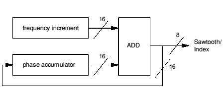
Schematic of accumulator/divisor oscillator
Register field assignment: Rp
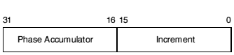
ADD Rp,Rp,Rp,LSL #16 ; phase accumulate
Changing parameters or the voice table being used is best done at or close to zero-crossing points, to avoid noise generation. If wavetables are arranged with zero-crossing aligned to the start and end of the table then it is simple to add a branch to appropriate code.
ADDS  Rp,Rp,Rp,LSL #16  ; phase accumulate
BCS   Update            ; only take branch if past zero crossing
Normally fixed-length (256-byte or a larger power of two) wavetables are used by most voice generator modules. The high bits of the phase accumulator are added to a wavetable base pointer to access the sample byte within the table:
For a 256-byte table:
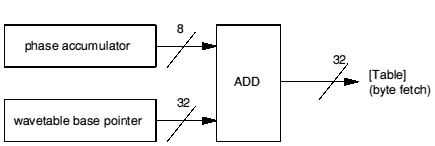
Schematic of wavetable access code
LDRB Rs,[Rt,Rp,LSR #24]
where the most significant 8 bits of Rp contain the Phase index, Rt is the Table base pointer, and Rs is the register used to store the sample.
If the overall volume setting changes, then your Update entry point will be called. You can cope with the change in two ways. The first is to re-scale all the values in the wavetable, using the SWI calls Sound_SoundLog or Sound_LogScale. This has the advantage that buffer filling is faster as the values are already scaled, but has the disadvantage that the wavetables might be stored to a lower resolution resulting in increased noise levels.
The alternative is to re-scale the values between reading them from the wavetable and outputting them, as in the example voice given later. The reverse then applies: buffer filling is slower, but noise is reduced. This method is preferred, so long as the algorithm is still able to fill the buffer within the required period.
The channel's volume setting should be used by all well-behaved Voice Generators. The volume is passed to the Voice Generator by the Channel Handler in the SCCB, as a signed 8 bit logarithm, but in a different format to that used by the VIDC chip:
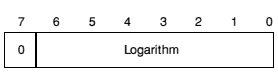
The coding is easiest if the values are treated as fractional quantities, and is then reduced to subtracting logarithms and checking for underflow:
Ra contains amplitude in range 0 to 127
Rs contains sample data in range -127 to +127 [sign bit LSB]
; do this each time Voice Generator is entered
RSB   Ra,Ra,#127         ; make attenuation factor
; do this inside loop, before each write to buffer
SUBS  Rs,Rs,Ra,LSL #1    ; note shift to convert to VIDC format
MOVMI Rs,#0              ; correct for underflow
Note - The example voice shows how this can be combined with use of the volume-scaled lookup table to scale for both the overall and channel volume on each fill.
Envelopes (if used) must be coded within the Voice Generator. A lookup table must be defined giving the envelope shape. This is then accessed in a similar manner to a wavetable, using the timbre phase accumulator passed in the SCCB. The sample byte is then scaled using this value, as shown above.
If you continue after a gate off, you must store your own copy of the volume, as any value in the SCCB will be overwritten.
Algorithms which work with linear integer arithmetic may use the Channel Handler linear-log table directly to fill buffers efficiently. The table is 8 Kbyte in length, to allow the full dynamic range of the VIDC sound digital to analogue converter to be utilised. The format is chosen to allow direct indexing using barrel-shifted 32-bit integer values. The values in the table are scaled according to the current volume setting.
; to access the lookup table pointer during initialisation:
        MOV     R0,#0
        MOV     R1,#0
        MOV     R2,#0
        MOV     R3,#0      ; get Channel Handler base
        MOV     R4,#0
        SWI     "XSound_Configure"
        BVS     error_return
        LDR     R8,[R3,#8] ; lin-to-log pointer
  ; in line buffer filling code:
  ; linear 32-bit value in R0
        LDRB    R0,[R8,R0,LSR #19] ; lin -> log
        STRB    R0,[R12],R11       ; output to DMA buffer
An efficient pseudo-random bit generator can be implemented using two internal registers. This provides noise which is necessary for some sounds, percussion in particular. One register is used as a multi-tap shift register, loaded with a seed value; the second is loaded with an XOR bit mask constant (&1D872B41). The sequence produced has a length of 4294967295. The random carry bit setting by the simple code fragment outlined below allows conditional execution on carry set (or cleared):
MOVS  R8,R8,LSL #1 ; set random carry
EORCS R8,R8,R9
xxxCC  ; do this...
yyyCS  ; ...or alternately this
This program shows a complete Voice Generator. It builds a wavetable containing a sine wave at maximum amplitude. Scaling is performed when the table is read:
 REM -> WaveVoice
 :
 DIM WaveTable% 255
 DIM Code%     4095
 :
 SYS "Sound_Volume",127 TO UserVolum
 FOR s%=0 TO 255
   SYS "Sound_SoundLog",&7FFFFFFF*SIN(2*PI*s%/256) TO WaveTable%?s%
 NEXT s% : REM build samples at full volum
 SYS "Sound_Volume",UserVolume TO UserVolum
 REM and restore volume to value on entry
 :
 FOR C=0 TO 2 STEP 2
 P%=Code%
 [ OPT C
 ;**************************************
 ;*   VOICE CO-ROUTINE CODE SEGMENT    *
 ;**************************************
 ; On installation, point Channel Handler voice
 ; pointers to this voice control block
 ; (return address always on top of stack)
 .VoiceBase
    B       Fill
    B       Fill               ; update entry
    B       GateOn
    B       GateOff
    B       Instance           ; Instantiate entry
    LDMFD   R13!,{PC}          ; Free entry
    LDMFD   R13!,{PC}          ; Initialise
    EQUD    VoiceName - VoiceBase
 ;
 .VoiceName EQUS "WaveVoice"
            EQUB 0
    ALIGN
 ;**************************************
 .LogAmpPtr EQUD 0
 .WaveBase  EQUD WaveTable%
 ;**************************************
 .Instance ; any instance must use volume scaled log amp table
    STMFD   R13!,{R0-R4}       ; save registers
    MOV     R0,#0
    MOV     R1,#0
    MOV     R2,#0
    MOV     R3,#0
    MOV     R4,#0
    SWI     "XSound_Configure"
    LDRVC   R0,[R3,#12]        ; get address of volume scaled log amp table
    STRVC   R0,LogAmpPtr       ; and stor
    STRVS   R0, [R13]          ; return error pointe
    LDMFD   R13!,{R0-R4,PC}    ; restore registers and return
 ;**************************************
 ;*  VOICE BUFFER FILL ROUTINES        *
 ;**************************************
 ; on entry:
 ;   r0-r8 available
 ;   r9  is SoundChannelControlBlock pointer
 ;   r10 DMA buffer limit (+1)
 ;   r11 DMA buffer interleave increment
 ;   r12 DMA buffer base pointer
 ;   r13 Sound system Stack with return address and flags
 ;     on top (must LDMFD R13!,{...,pc}
 ; NO r14 - IRQs are enabled and r14 is not usable
 .GateOn
    LDR     R0,WaveBase        ; wavetable base
    STR     R0,[R9,#16]        ; set up in SCCB as working register 5
    LDR     R0,LogAmpPtr       ; volume scaled log amp table
    STR     R0,[R9,#20]        ; set up as working register 6
 ;**************************************
 .Fill
    LDMIA   R9,{R1-R6}         ; pick up working registers from SCCB
    AND     R1,R1,#&7F         ; mask R1 so only channel amplitude remain
 ; R1 is amp (0-127)       R2 is pitch phase acc
 ; R3 is timbre phase acc  R4 is duration
 ; R5 is wavetable base    R6 is amp table bas
                               ; move sign bit -> VIDC format lo
    LDRB    R1,[R6,R1,LSL #1]  ; and lookup amp scaled to overall volume
    MOV     R1,R1,LSR #1       ; move sign bit back again
    RSB     R1,R1,#127         ; make attenuation factor
 .FillLoop
    ADD     R2,R2,R2,LSL #16   ; advance waveform phase
    LDRB    R0,[R5,R2,LSR #24] ; get wave sample
    SUBS    R0,R0,R1,LSL #1    ; scale amplitude for overall & channel volumes
    MOVMI   R0,#0              ; and correct underflow
    STRB    R0,[R12],R11       ; generate output sample
    ADD     R2,R2,R2,LSL #16   ; repeated in line four times...
    LDRB    R0,[R5,R2,LSR #24]
    SUBS    R0,R0,R1,LSL #1
    MOVMI   R0,#0
    STRB    R0,[R12],R11
    ADD     R2,R2,R2,LSL #16
    LDRB    R0,[R5,R2,LSR #24]
    SUBS    R0,R0,R1,LSL #1
    MOVMI   R0,#0
    STRB    R0,[R12],R11
    ADD     R2,R2,R2,LSL #16
    LDRB    R0,[R5,R2,LSR #24]
    SUBS    R0,R0,R1,LSL #1
    MOVMI   R0,#0
    STRB    R0,[R12],R11       ; end of repeats..
    CMP     R12,R10            ; check for end of buffer fill
    BLT     FillLoop           ; loop if not
 ; check for end of note
    SUBS    R4,R4,#1           ; decrement centisec count
    STMIB   R9,{R2-R5}         ; save registers to SCC
    MOVPL   R0,#%00001000      ; voice active if still duration left
    MOVMI   R0,#%00000010      ; else force flush
    LDMFD   R13!,{PC}          ; return to level 1
 ;**************************************
 .GateOff
    MOV     R0,#0
 .FlushLoop
    STRB    R0,[R12],R11       ; fill buffer with zeroes
    STRB    R0,[R12],R11
    STRB    R0,[R12],R11
    STRB    R0,[R12],R11
    CMP     R12,R10
    BLT     FlushLoop
 ; CAUSE level 1 TO FLUSH once more
    MOV     R0,#%00000001      ; set flag to flush one more buffer
    LDMFD   R13!,{PC}          ; return to level 1
 ]
 NEXT C
 :
 DIM OldVoice%(8)
 SYS "Sound_InstallVoice",VoiceBase,0 TO a%,Voice%
 FOR v%=1 TO 8
   SYS "Sound_AttachVoice",v%,0 TO z%,OldVoice%(v%)
   VOICE v%,"WaveVoice"
 NEXT
 :
 ON ERROR PROCRestoreSound : END
 :
 VOICES 8
 *voices
 SOUND 1,&17F,53,10 :REM activate channel 1!
 PRINT''"any key to make a noise, <ESCAPE> to finish"
 :
 C%=1
 REPEAT
   K%=INKEY(1)
   IF K%>0 THEN
     SOUND C%,&17F,K%,100
     C%+=1 : IF C%>8 THEN C%=1
   ENDIF
 UNTIL 0
 :
 DEF PROCRestoreSound
   ON ERROR OFF
   REPORT:PRINT ERL
   SYS "Sound_RemoveVoice",0,Voice%
   FOR v%=1 TO 8
     SYS "Sound_AttachVoice",v%,OldVoice%(v%)
   NEXT
   VOICES 1
   *voices
   PRINT''
 ENDPROC