
|
www.riscos.com Technical Support: |
Though strictly speaking part of the character output system, the VDU drivers are quite complex, and deserve a chapter of their own. This chapter introduces the important concepts relating to the VDU, such as:
The Character Output described how to write to the VDU. This chapter describes what special effects occur when particular characters are sent.
There are also a large number of VDU specific commands that allow fine control of its operation.
There are five important aspects of VDU interaction which are not described in this chapter. These are:
These are implemented as modules separate from the RISC OS kernel, and are described in their own chapters.
The most important call relating to the VDU is OS_WriteC, as this is used in nearly all programs which have to output to the screen. Other calls can be used for more direct control of the VDU facilities.
The VDU display on RISC OS comes from the VIDC chip. This reads the contents of a block of memory and converts it into a form that can drive a video monitor.
This chapter differs from others in this manual in that, in addition to a list of SWIs and *commands, there is also a list of VDU commands. To issue VDU commands, simply use OS_WriteC to send characters to the VDU stream. All characters are strictly VDU commands, but those between 0 and 31, and 127 are of special interest because they cause special actions to take place. The others are simply printed on the screen as a character.
These special characters are used as commands. They can be followed by a sequence of characters, the length of which depends on the command. In some cases, the character on its own is sufficient, but it can require up to 9 following bytes to complete the command. These bytes are queued until the required number are in the queue before the command is executed.
To represent these sequences of characters sent to the VDU using OS_WriteC, a shorthand is used in this chapter. You will see VDU followed by numbers separated by commas. This represents each character being sent through OS_WriteC.
For example, VDU 65 sends character 65, an ASCII 'A', to OS_WriteC. VDU 17,3 sends character 17 followed by character 3.
RISC OS supports many different ways of displaying information on the screen. Each of these different ways is called a mode. The exact number of modes available depends on the type of monitor you have. They are all bit-mapped displays, in which one or more bits of screen memory control the colour of a dot, or pixel, on the screen. Two main characteristics distinguish the modes.
Between them, the resolution and number of colours determine the amount of screen memory used by a mode.
A complete list of the available modes is given in the description of VDU 22, which is the command that changes modes.
There are two distinct types of object that the VDU drivers can draw onto the screen.
Different commands will act to either text or graphics areas. Each has a window, or area where their output will go. After a mode change, both text and graphic windows fill the screen and overlap each other exactly. There is no conflict in having them overlap, since the window is just a declaration of boundaries. Either window can be changed at any time to be any size. Any output to a window will be clipped to it. For example, if only part of a line appears in the graphics window, then only that part will be shown and the rest ignored.
A cursor is the place at which the next output will go. There are independent text and graphics cursors, which must remain inside their relevant window.
Various control commands are provided to affect the output in text and graphics windows. Examples of such actions are:
Text characters are patterns of pixels which are positioned on the screen at character-aligned positions. That is, the screen is treated like an array of character sized boxes, into which can go any printable character.
All text display is normally confined to the text window. All scrolling is confined to this region, sometimes called the scrolling window, because text can be scrolled within it. The graphics window cannot be scrolled automatically; but you can use block move to perform scrolling.
The text cursor shows the position on the screen of the next character to be displayed. This is usually a flashing underline. There can be a second cursor which is used with cursor editing (this is described later).
Note that there are some screen modes that will only display text.
The graphics VDU handles the drawing of objects such as points, lines, circles, ellipses, etc. The graphics window, like the text window, starts as the whole screen after a mode change. The graphics cursor, which is invisible, marks the last point at which a graphics operation ended.
The VDU driver can be configured to print text at the graphics cursor instead of the text cursor. This means that text will be drawn using the current graphics cursor for positioning, and using the graphics colour, etc. The advantage of this mode is that it enables characters to be drawn at any pixel alignment, and to be clipped to the graphics window (important when you use the Wimp environment). The disadvantages are that the characters take longer to draw and scrolling is not available. Generally, when text is printed at the graphics cursor, this is referred to as VDU 5 mode because this is the command that enables it.
Although the cursor editing facility isn't strictly part of the VDU drivers, its presence does have some interaction with the VDU.
Usually there is only one text cursor, but when you press one of the four cursor direction keys, cursor editing mode starts. There are now two cursors; the output cursor, which is now shown as a steady 'blob', and the input cursor, which is an underline flashing at twice the usual rate. The Copy key has the action of copying what is under the input cursor to the output cursor as if it was typed.
See the chapter entitled Character Input for a full description of these keys and their control.
Cursor editing mode is not available in VDU 5 mode, and it is cancelled when you send an ASCII 13 (carriage return) to the VDU stream. This is usually done when you press Return at the end of an input line.
The number of colours available on the screen at any time is either 2, 4, 16 or 256. When you first enter a mode, the default colours are assigned. These can subsequently be changed with the palette.
In 256 colour modes, there are 64 different colours, and each colour may have four different shades, resulting in a total of 256 different colours.
You may choose to display your text or graphics in a different colour from the defaults. To do this, there are commands to change the foreground and background of each. Usually, the foreground colour is that in which the text or graphics drawing is done, and the background colour is used for all other drawing, such as a screen clear. RISC OS can be changed so that the background colour is used for drawing if required.
Another important part of the VDU is the palette. This is the control of what colours appear on the screen. The palette is a table built into the VIDC chip which determines the relationship between the colour number stored in the screen memory (logical colour), and the actual colour information sent to the monitor (physical colour). Care should be taken not to confuse logical and physical colours. Thus, while colour 0 on RISC OS is black by default, it can be made to be any colour by changing how the palette maps it.
The palette is programmed in terms of the intensity of the signal on each of the red, green and blue guns in a colour monitor. These intensities have 4 bits each, which gives twelve bits altogether, hence the 4096 (212) physical colours. Flashing colours are accomplished by a logical colour having 2 physical colours associated with it. These are swapped at a programmable rate, causing flashing.
The palette also controls the colour of the border around the screen and the colours of the mouse pointer. These can be set independently of any other colour on the screen.
In 256 colour modes, each pixel is represented by an 8-bit value. Six bits are the logical colour, and the other two bits are the tint. The tint is a direct control of the amount of grey which is added to the base colour, to one of 4 levels.
The six bits in the logical colour set the basic colour from the range of different shades of colours provided by the palette. The tint is the fine control within this range.
The Extended Colour Fill patterns are a means of increasing the apparent number of colours by producing a fine chequerboard mix of colours. This is of most use in modes where there are few colours available, because it gives the effect of having more colours on the screen than there are.
Four different ECF patterns are provided, and can be independently defined.
Normally, the origin of the ECF patterns is based on the bottom left corner of the screen. This can be changed, so that it aligns with any point on the screen, such as the current graphics window.
The mouse is a device that is moved on a surface, rolling an internal ball, usually with several buttons. The pointer is a reflection on the screen of the mouse's movements. Normally, it appears as a small arrow, but can be programmed to be any shape. It is also possible to disconnect the pointer from the mouse and move the pointer to where the program wants it to be. This is useful when switching between windows under program control.
RISC OS provides control over how much the pointer moves in response to a mouse movement. This sensitivity control can be useful in situations where fine or coarse movement is required by different programs.
Full control is given over how video information is generated. Depending on how it looks on screen, the display can be shifted up or down. Some monitors do not allow for this adjustment, so this facility is provided.
Also, the interlace can be switched on or off. Interlace means that images sent to a monitor alternate one scan line up and down on alternate frames. On a monitor which has a long persistence phosphor (images take some time to fade), an interlaced image eliminates the 'lined' effect of a screen image. On a short persistence screen interlace can cause a flicker, because the first image has faded before the second one is finished.
RISC OS supports many different kinds of monitor. Depending on the type of monitor used, only a subset of all possible modes are available on it. Thus there is a command to set which monitor is connected, so that incorrect modes are not accidentally entered.
Normally, there is one bank of memory that is used for the screen. If it is changed, then this is reflected on the screen as it is refreshed by VIDC. Sometimes it is useful to write to one bank of screen memory, while another is displayed and then swap when finished. This produces an 'instant draw' effect, which is visually pleasing.
Whilst normally only two banks would be used for this kind of application, you can have as many banks as will fit in the allocated screen RAM area. This requires copies of the screen RAM requirements for each bank. For example, with two banks of screen memory, an 80K mode will require 160K.
Many different kinds of things can generate output on the screen, or more strictly speaking, the current screen bank. Text or graphics can be written, and many commands exist to alter where and how output will appear on the screen.
Sending printable characters through OS_WriteC will result in it appearing at the text cursor position in the current window. It will wrap around to following lines when it reaches the right hand side of the window. Certain control commands can move the text cursor in all directions or to a given place in the window. Usually, the cursor moves right after a character is printed. This can be changed so it moves in any of the four directions.
Many different kinds of graphics can be put onto the screen, such as:
See the chapter entitled Sprites to see how any sized array of pixels can be written to the screen.
As well as different shapes, there is control over how it is written over what is already on the screen. It can be configured to:
and so on.
As well as having control over the colour and writing mode, you can use any of the ECF patterns to write with.
The graphics or text windows can either be completely or partially cleared. This will be done with the current graphics or text background colour as appropriate.
There is a method under RISC OS of waiting until a Vsync event occurs and then writing to the screen. This can make screen update very smooth, as writing to the screen memory does not clash with the VIDC chip reading it to send to the monitor. If they do clash, then a 'tearing' can appear briefly. This is because one part of the memory being written to is displayed in its old state and the other part in the new.
Unless you plan to use multiple paging techniques, then this is a good way of achieving smooth animation.
As well as writing to the screen, it is possible to read some information back from it. There is a command to read a character from under the text cursor and work out what its ASCII value is. Cursor editing uses this facility.
You can also read the logical colour and tint of a point. Given that there is another call to return the palette setting for a colour, it is easy to combine the two and work out the 'real' colour of pixels on the screen.
The screen can be saved as a file, which can be subsequently treated as a sprite, or edited with Paint for example. There is a complementary command to load it back onto the screen.
There are a number of calls to get all kinds of information about the configuration and status of the VDU driver. Here is some of the information that can be read:
As mentioned earlier, 'VDU' followed by a series of numbers separated by commas is used in this chapter to represent a character being sent to OS_WriteC. For convenience, we will use the shortcuts that BBC BASIC uses with its VDU statement. Here is a brief reminder of the syntax of that statement:
Of course, as long as the correct characters are sent to the VDU, it doesn't matter how they get there. For example, an assembly language equivalent to VDU 12 (clear screen) is:
SWI OS_WriteI+12
The effect is the same in both cases.
When changing mode, a great many things are initialised. For a complete list of these and other mode notes, see VDU 22.
*Configure Mode will set up the screen mode to be used after a hard reset.
When a program wishes to change mode, it must check that there is enough memory allocated for the screen for that mode and that the monitor being used is compatible with the mode. OS_CheckModeValid must be called to check these two things. If you don't, then VDU 22 will do it anyway, but it is better for the program to be aware of what's happening. If the mode requested cannot be used, OS_CheckModeValid will also return a suggestion for a mode to use in place of it.
The computer can adjust its output to suit its attached monitor in a number of ways.
*Configure MonitorType is used to tell RISC OS to auto-detect the type of monitor connected from its lead, or - should it be unable to do so from hardware - to tell it explicitly what kind of monitor is attached. This command allows the system to subsequently disallow any modes that are not compatible with the attached monitor.
*Configure Sync will set up the vertical sync output of the video connector to be auto-detected, or to be vertical or composite sync. Different monitors may require either of these, though most use composite sync.
*Configure TV, *TV and OS_Byte 144 can all adjust the position of the video output up or down by several lines, and switch interlace on and off. VDU 23,0 can also control the interlace setting.
There are two main commands that can be used to handle multiple banks of screen memory. OS_Byte 112 selects which bank of memory to send VDU output to. OS_Byte 113 selects which bank of memory is used by the VIDC hardware to write out to the screen. By using these two, it is simple to swap screens at will.
OS_Byte 250 reads the current OS_Byte 112 setting, and OS_Byte 251 reads the current OS_Byte 113 setting.
In order to use multiple banks, you will probably have to use *Configure ScreenSize to set the amount of memory to reserve for all the banks.
*Shadow exists mainly for compatibility with BBC/Master operating systems. Under RISC OS, it can select between two banks of memory to be used on the next mode change. OS_Byte 114 has the same effect as *Shadow. OS_Bytes 112 and 113 support the shadow system, but you are better off using bank numbers directly.
For those who want low level access to screen banks, OS_Word 22 allows setting the addresses of the VDU bank and the VIDC bank directly.
These are the colours as set up after a mode change:
0 = black
1 = white
0 = black
1 = red
2 = yellow
3 = white
0 = black
1 = red
2 = green
3 = yellow
4 = blue
5 = magenta
6 = cyan
7 = white
8 = flashing black-white
9 = flashing red-cyan
10 = flashing green-magenta
11 = flashing yellow-blue
12 = flashing blue-yellow
13 = flashing magenta-green
14 = flashing cyan-red
15 = flashing white-black
256 colour modes are treated differently from the others. Instead of using the standard 16 entry physical colour table, there are two systems which are used by different commands. The internal format is the less easy to use of the two. In it, the bits are structured as follows:
| Bit | Meaning |
|---|---|
| 0 | Bit 0 of palette index |
| 1 | Bit 1 of palette index |
| 2 | Bit 2 of palette index |
| 3 | Bit 3 of palette index |
| 4 | Red bit 3 (high) |
| 5 | Green bit 2 |
| 6 | Green bit 3 (high) |
| 7 | Blue bit 3 (high) |
where the palette index (0 - 15) controls which VIDC palette entry is used, but with some bits of the palette entry then being overridden by the top 4 bits of the memory byte. With the default palette setting, this becomes:
| Bit | Meaning |
|---|---|
| 0 | Tint bit 0 (red + green + blue bit 0) |
| 1 | Tint bit 1 (red + green + blue bit 1) |
| 2 | Red bit 2 |
| 3 | Blue bit 2 |
| 4 | Red bit 3 (high) |
| 5 | Green bit 2 |
| 6 | Green bit 3 (high) |
| 7 | Blue bit 3 (high) |
Each primary colour has 4 bits of intensity, but the two least significant bits (the tint bits) are shared between the three colours. Therefore, some intensities of a primary colour (for example, red) can only be obtained at the expense of adding in a certain amount of grey.
The second form for 256 colours, which is used by some commands is structured as follows:
| Bit | Meaning |
|---|---|
| 0 | Red bit 2 |
| 1 | Red bit 3 (high) |
| 2 | Green bit 2 |
| 3 | Green bit 3 (high) |
| 4 | Blue bit 2 |
| 5 | Blue bit 3 (high) |
| 6 | Tint bit 0 (red + green + blue bit 0) |
| 7 | Tint bit 1 (red + green + blue bit 1) |
The tint is controlled separately in most commands; bits 6 and 7 are only used in the native ECF setting, which is not often used in 256 colour modes.
This format is converted into the internal format when stored, because that is what the VIDC hardware recognises.
VDU 17 can be used to change the text colour. VDU 23,17,5| will exchange the text foreground and background colours.
VDU 18 can change the graphics colour, and much more than just that. Because graphics can interact with what is already is on the screen, then VDU 18 can set up the graphics to be ORd, ANDed, XORd, inverted and so on.
In 256 colour modes, VDU 23,17,0 - 3 can be used to set the tints to be used when next printing/plotting.
VDU 19 can be used to change the way that the palette defines the logical to physical colour relationship. It has many modes and as well as changing the logical colours, can also set the border, flashing and pointer colours. OS_Word 12 can also be used to write the palette.
VDU 20 will return the palette to the condition that it was just after a mode change. This would be used by a program just before finishing, if it had altered the palette during running.
If you want to read the palette setting of a colour, OS_ReadPalette or the BBC/Master compatible OS_Word 11 can be used.
RISC OS will swap two colours at a programmed interval. If they are the same colour, then there is no noticeable effect. If they are different, then flashing will result. VDU 19 can individually set these colours to be any colour from the palette.
The speed at which flashing occurs can be controlled by OS_Bytes 9 and 10. They set the duration in video frames. VDU 23,9 and VDU 23,10 have the same effect as these calls. The duration settings can be read by OS_Bytes 194 and 195.
OS_Byte 193 allows a program to read or alter the flash counter. This is a decrementing counter that swaps colours when the count reaches zero.
There are several different ways of changing ECF patterns. The main command is VDU 23,2-5. This can operate in two modes depending on the setting of VDU 23,17,4. Also, VDU 23,12-15 can be used for simpler patterns.
Both commands are passed 8 bytes that define the pattern. The number of pixels depends on how many colours are available in the screen mode you are using:
| Colours available | Number of pixels set by each line | |
|---|---|---|
| VDU 23,2-5 | VDU 23,12-15 | |
| 2 | 8 | 2 |
| 4 | 4 | 2 |
| 16 | 2 | 2 |
| 256 | 1 | 1 |
You can see that while the number of pixels in the pattern diminishes, the number of potential colours increases.
As you can see, in a 256 colour mode, the pattern is simply a colour description for each line. VDU 23,2-5 uses the internal 256 colour map, while VDU 23,12-15 uses the simpler colour map. When stored, the internal form is used. This should be borne in mind if you use OS_Word 10 to read the ECF definitions.
This call uses a simpler pattern. The 8 parameters passed form a pattern as follows:
So it describes a simple 2 by 4 pattern for all but 256 colour modes. Here it is one colour per line, for all 8 lines, like VDU 23,2-5.
This call is more complex. It uses one line per parameter, and there is a direct trade-off between colours and resolution. Thus, for a 2 colour mode, it can display an 8 by 8 pattern of on or off pixels, in 256 colour mode, it can only generate 8 lines of a single different colour each.
VDU 23,17,4 is used to select between BBC/Master compatible mode and native RISC OS mode. These modes describe how ECF colour descriptions are mixed when using VDU 23,2-5. For some examples, see the chapter entitled Application Notes.
VDU 23,11 will reset the ECF pattern definitions to their default values. It will also reset the VDU 23,17,4 flag to the default BBC/Master compatible state.
By default, patterns are written as if their bottom left hand corner is aligned with the bottom left hand corner of the screen. Using OS_SetECFOrigin, you can instead align an ECF pattern to any point on the screen, or to an object such as the graphics window. VDU 23,17,6 has the same effect as this call.
The bell can be made to sound by sending a VDU 7 to OS_WriteC.
To configure how it will sound:
*Configure Quiet will select a quiet volume, while *Configure Loud will select a loud volume.
VDU 5 will link text and graphics cursors and cause all subsequent output to be printed at the graphics cursor position. This command can be cancelled using VDU 4. The text input cursor is normally displayed unless disabled by VDU 23,1. Both this and VDU 23,0 can be used to change the appearance of the cursor.
There are a number of VDU commands that affect the position of the text cursor directly:
The position of the text cursor can be read with OS_Byte 134. If cursor editing is in progress, then OS_Byte 165 can be used to read the position of the output cursor, usually displayed as a solid blob.
Normally, when a character is printed, the cursor currently used will move to the right. This action can be controlled by VDU 23,16. It can set the cursor to move in any of four directions. It also controls how cursors act at the end of lines, and so on.
OS_RemoveCursors will remove the input and output cursors and store their state internally. A subsequent call to OS_RestoreCursors will restore them exactly. These calls are used mainly by low-level draw routines to avoid mixing the cursors with what is drawn on the screen.
OS_Word 13 will return the current and previous graphics cursor positions. Using OS_ReadVduVariables, even earlier coordinates can be read.
When a mouse button is pressed or released a record is kept in the mouse buffer. OS_Mouse will read a mouse record from this buffer. It stores the position of the mouse, the state of its buttons and the time the record was put into the buffer. OS_Byte 128 can also be used for this as well as reading how much free space is in the mouse buffer.
OS_Word 21,3 will set the mouse position, so subsequent writes to the mouse buffer will assume the mouse is at the specified location, and move from there.
OS_Word 21,4 will read the unbuffered mouse position. That is, where it is at the moment of calling this function. This bypasses the buffer, so subsequent reads of the buffer may not tie up with this position. It is better to use one or the other method exclusively in a program.
The ratio of mouse movement to pointer movement on screen can be controlled by OS_Word 21,2 or permanently set by *Configure MouseStep.
The pointer that appears on the screen can be defined in four shapes. OS_Word 21,0 can define the shape and colour of each of these. OS_Byte 106 is used to select which pointer to use, or switch it off completely. *Pointer can also be used to switch it on or off.
The pointer will be confined to the box defined by OS_Word 21,1. This would usually be set to the graphics window.
The pointer's position on the screen can be set with OS_Word 21,5 and read with OS_Word 21,6.
There are many ways of extracting information about the state and configuration of the VDU system.
OS_Byte 217 will read the number of lines since the display was last stopped scrolling if it was in paged mode.
OS_Byte 218 returns how many bytes are in the VDU queue. This is used when a multiple byte VDU command is being collected.
OS_Byte 163 will return the current dot-dash line length and the amount of memory allocated for sprites. It can also set the dot-dash length.
OS_ReadDynamicArea is a better way to read the amount of memory allocated for system sprites - this call will also return the memory allocated for screen bank use.
OS_Byte 117 reads the VDU status. This involves:
OS_ReadVduVariables provides a large number of variables that can be read. OS_Byte 160 is a subset of this, kept for BBC/Master compatibility reasons. Almost all information about windows, cursors and colours can be accessed here. Two special variables provided are a pointer to a fast horizontal line draw routine and access to colour blocks.
OS_ReadModeVariable returns the fixed information about a mode, such as how many pixels across and down it is, and how many colours it supports.
OS_Byte 135 will read the ASCII value of the character at the text cursor position and also reads the current screen mode.
OS_ReadPoint will read the logical colour of a pixel. OS_Word 9 performs much the same function, but is kept mainly for compatibility with BBC/Master series.
*ScreenSave will copy the screen contents into a file where it can subsequently be edited with Paint or reloaded to the screen with *ScreenLoad.
Output to the screen can be disabled by VDU 21. It can be restored by VDU 6.
VDU 26 will restore the graphics and text windows to their default states. That is, both filling the screen.
Text can be sent to the screen with any VDU command from 32 to 255, excepting 127 which is the delete command.
VDU 28 defines the text window. VDU 12 will clear the window that the text cursor is in. After a VDU 12, the text cursor is moved to its home position, usually the top left hand corner. VDU 23,8 will clear a block within the text window.
Paged mode means that when about 75% of a screenful has been shown, then the system will pause and wait for Shift to be pressed before starting again. This stops text being lost from scrolling off the top of the screen too quickly Paged mode can be enabled by VDU 14 and disabled with VDU 15. By default, paged mode is off.
*Configure Scroll and NoScroll configure whether text will scroll when it reaches the bottom of the text window. This means that when NoScroll is set a character can be printed at the bottom right of the screen without immediately scrolling the screen. This feature can also be controlled with VDU 23,16 and allows a full screen of text to be simply printed.
VDU 23,7 can scroll the text window or the whole screen in any direction.
In VDU 5 mode, it is possible to change the size and spacing of text with VDU 23,17,7. This is how you would generate a message with large gaps between the characters.
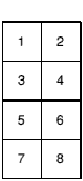
Each printable character (one that is not a command) is an array of 8 by 8 pixels that is defined in the shape of standard ASCII and ISO characters. All of these characters can be redefined to be any pattern.
To change the definition of a printable character, VDU 23,32-255 must be used. The character number that you wish to redefine is the second parameter, in the range 32-255. It is followed by 8 bytes that define the bit pattern to be used.
OS_Byte 20 will reset character definitions 32 - 127 to their default. OS_Byte 25 will reset a given group of them. OS_Word 10 can read the definition of any character from the current system font.
VDU 1 will send the following character to the printer stream. VDU 2 will enable the stream, so that all characters sent to the VDU are also sent to the printer stream. This state can be disabled by VDU 3.
VDU 24 will define the position of the graphics window. VDU 16 will clear it to the current graphics background colour.
VDU 25 is the main graphics plot command. OS_Plot has the same effect as it, but is much faster, avoiding the delays inherent in the VDU stream. They both have a type parameter followed by x and y coordinates. The type covers moving the graphics cursor, plotting points, lines (solid and dotted), triangles, rectangles, parallelograms, circles, arcs, sectors, segments, ellipses and other graphic forms. These figures can be hollow or filled with the graphics foreground colour. It handles relative or absolute drawing That is, the x and y are relative to the current x and y or moving to a new absolute position on the screen.
When plotting dotted lines, the default pattern is a dot-space pattern repeated. This can be changed to any pattern. VDU 23,6 is passed 8 bytes that define a pattern up to 64 bits in length to be repeated. OS_Byte 163 sets how many bits are to be used. Simple patterns like &FF (solid line), &AA (the default dot-space) and &EE (dashed line: dot-dot-dot-space) can be used or any more complex pattern up to 64 bits in length. OS_Word 10 can read the current definition.
VDU 29 sets the graphics origin. This is the point on the screen that becomes the 0,0 point for all subsequent graphics operations.
OS_ChangedBox will tell you what area of the screen has been changed. This can be used to reduce the amount of redrawing that needs to be done by an application.
*ScreenLoad complements *ScreenSave, discussed earlier and load a file into the screen memory.
OS_Byte 19 will wait until a Vsync occurs before returning. This allows programs that are quick enough to write to the screen without any kind of flickering or tearing of images.
This is described fully in the Screen memory.
VDU 0
--
VDU 0 does nothing. It is this that enables the '|' character in the VDU statement to work. Any of the nine zeros that are sent which aren't required by the current VDU command are 'swallowed up'.
Next character to printer only
VDU 1,character
character - to send to the printer stream
VDU 1 sends the next character to the printer stream only, provided that the printer has been enabled by VDU 2. Otherwise, the next character is ignored. This enables the printer ignore character, and any other character which is not usually passed on by the VDU printer driver, to be sent to the printer through the VDU.
VDU 1,10 - Send a linefeed to the printer stream, if enabled
Enable printer stream
VDU 2
--
VDU 2 enables the printer stream. After this call, most characters sent to the screen will also be sent to the currently selected printer device. OS_Byte 5 controls this, as described on OS_Byte 5. Only characters in the following ranges are sent to the printer: 32 - 126, 128 - 255 (ie the printable characters), 8 - 13 (backspace, horizontal tab, linefeed, vertical tab, form feed and carriage return, respectively). No multi-byte control sequences, except the argument of VDU 1, are sent to the printer.
Even if the VDU drivers are disabled (using VDU 21) the characters sent to the VDU drivers will still be sent to the printer although they will no longer affect the screen. However, if the VDU is disabled using OS_Byte 3, then VDU 2 printing will not take place.
The effect of VDU 2 can be cancelled using VDU 3.
You can determine whether VDU printing is enabled using OS_Byte 117.
Disable printer stream
VDU 3
--
VDU 3 cancels the effects of VDU 2 so that all subsequent printable characters are not passed through the kernel printer driver.
Split cursors
VDU 4
--
VDU 4 cancels VDU 5 mode. It causes all subsequent printable characters to be printed at the current text cursor position using the current text foreground and background colours. The text cursor is normally displayed (unless it has been disabled using VDU 23,1) and after each character has been printed the cursor moves on by one character. The direction of cursor movement is normally to the right but may be altered using VDU 23,16.
After a character has been printed at the end of a row (or column if vertical printing is used) the cursor moves on to the start of the next screen line (or column), scrolling the screen when there are no more rows (or columns), providing scrolling is enabled. Again, you can use VDU 23,16 to enable or disable scrolling. Cursor editing is allowed in this mode.
You can determine whether the cursors are split or joined using OS_Byte 117.
Join cursors
VDU 5
--
This enters VDU 5 mode. It links the text and graphics cursors and causes all subsequent printable characters to be printed at the current graphics cursor position, the topmost row, lefthand edge of the character being placed there. Characters are displayed in the current graphics foreground colour using the current graphics action. The background pixels in the character shape are not plotted.
You can set the character sizing and spacing using VDU 23,17,7...
After the character has been printed, the graphics cursor is moved by one character position. The direction of cursor movement is normally to the right but may be altered (using VDU 23,16). It moves to a new row (or column if vertical printing is being used) when necessary, or to the opposite corner of the graphics window if there are no more rows (or columns). Scrolling does not occur.
This command allows characters to be placed at any position on the screen, but means that the text is printed somewhat slower than when the cursors are split. In addition, each character is superimposed onto the existing text or graphics. Hence, printing a backspace character followed by a space moves the graphics cursor back by one character and then superimposes a space onto the character already there, thereby leaving it unaltered.
Cursor editing is not possible in this mode.
VDU 5 has no effect in text-only or Teletext modes. In other modes it may be cancelled using VDU 4.
VDU 6
--
VDU 6 restores the functions of the VDU driver after it has been disabled by VDU 21. It causes all subsequent printable characters to be sent to the screen and control sequences to be obeyed.
You can determine whether the VDU is enabled or disabled using OS_Byte 117.
VDU 7
--
VDU 7 generates the current bell sound. The initial default is specified by *Configure Loud/Quiet and *Configure SoundDefault; you may subsequently alter it using OS_Bytes 211 - 214.
VDU 8
--
VDU 8 causes either the text cursor (by default) or the graphics cursor (in VDU 5 mode) to be moved back one character position (ie in the negative x direction). This normally means moving it to the left but will be different if the direction of cursor movement is altered (using VDU 23,16).
If the cursor was at the start of a row (or column if vertical printing is used) then it is moved back to the end of the previous row (or column), scrolling the screen if necessary. It does not cause the last character to be deleted.
VDU 9
--
VDU 9 causes either the text cursor (by default) or the graphics cursor (in VDU 5 mode) to be moved on one character position (ie in the positive x direction). This normally means moving it to the right but is different if the direction of cursor movement is altered (using VDU 23,16).
If the cursor was at the end of a row (or column if vertical printing is used) then it is moved on to the start of the next row (or column), scrolling the screen if necessary.
VDU 10
--
VDU 10 causes either the text cursor (by default) or the graphics cursor (in VDU 5 mode) to be moved on one line (ie in the positive y direction). This normally means moving it down but is different if the direction of cursor movement has been altered (using VDU 23,16).
If the cursor was on the last line then the screen will be scrolled provided that scrolling is enabled.
VDU 11
--
VDU 11 causes either the text cursor (by default) or the graphics cursor (in VDU 5 mode) to be moved back one line (ie in the negative y direction). This normally means moving it up but will be different if the direction of cursor movement has been altered (using VDU 23,16).
If the cursor was on the first line then the screen will be scrolled, if scrolling is enabled.
VDU 12
--
By default, VDU 12 clears either the current text window or, in VDU 5 mode, the current graphics window to the current text or graphics background colour respectively. The text or graphics cursor is moved to the text home position (see VDU 30).
When sent to a printer, this character generally causes a new page to be started.
VDU 13
--
VDU 13 causes the text cursor or, in VDU 5 mode, the graphics cursor to be moved to the negative x edge of the relevant window at the same y value. The negative x edge is normally the left edge but it may be changed using VDU 23,16.
When sent to a printer, this character generally causes the print head to move to the start of the current line. Additionally, some printers may also generate a linefeed.
VDU 14
--
VDU 14 causes the screen display to wait for Shift to be pressed before the next scroll and periodically thereafter. Normally, approximately 75% of the number of lines in the current window is scrolled before it waits again. The effects of the command may be cancelled using VDU 15.
OS_Byte 117 may be used to determine whether paged mode is enabled. See also OS_Byte 217.
VDU 15
--
VDU 15 cancels the effect of VDU 14 so that scrolling is unrestricted.
VDU 16
--
VDU 16 clears the current graphics window to the current graphics background colour using the graphics background action. It does not affect the position of the graphics cursor.
VDU 17,colour
colour - logical text colour
VDU 17 is used to assign a logical colour to either the text foreground or background according to the value of colour, as follows:
| Value | Colour |
|---|---|
| 0 - 127 | foreground |
| 128 - 255 | background (colour in range 0 - 127) |
If the absolute value of the parameter lies outside the allowed set for the current mode, it is treated MOD (the number of colours - 64 in 256 colour mode) so that it lies within that range. For example, in mode 1, which allows four colours, the commands VDU 17,9 and VDU 17,5 are equivalent to VDU 17,1.
The interpretation of colour depends on the type of mode:
| Colours | colour parameter meaning | |
|---|---|---|
| 2,4,16 | Logical colour for that pixel | |
| 256 | Bottom 6 bits of colour provide colour information:
Bit 4 - Blue bit 2 Bit 3 - Green bit 3 Bit 2 - Green bit 2 Bit 1 - Red bit 3 Bit 0 - Red bit 2 | |
This allows 64 different colours to be obtained. Each of these can be used in one of four different tints, giving 256 available shades. See VDU 23,17 for more details. The current text colours may be read using OS_ReadVduVariables.
VDU 18,action,colour
action - operation to perform
colour - colour to use
VDU 18 is used to define either the graphics foreground colour or the graphics background colour, and the way in which it is to be plotted on the screen.
The graphics plotting action is determined by action as follows:
| Value | Action |
|---|---|
| 0 | Overwrite colour on screen with colour |
| 1 | OR colour on screen with colour |
| 2 | AND colour on screen with colour |
| 3 | exclusive OR colour on screen with colour |
| 4 | Invert colour on screen |
| 5 | Leave colour on screen unchanged |
| 6 | AND colour on screen with (NOT colour) |
| 7 | OR colour on screen with (NOT colour) |
| 8 - 15 | As 0 to 7, but background colour is transparent |
| 16 - 31 | Colour pattern 1 using action 0 - 15 |
| 32 - 47 | Colour pattern 2 using action 0 - 15 |
| 48 - 63 | Colour pattern 3 using action 0 - 15 |
| 64 - 79 | Colour pattern 4 using action 0 - 15 |
| 80 - 95 | Giant colour pattern (patterns 1 - 4 placed side by side) |
The range 8 - 15 is used in the following circumstances:
These actions are also used in colour pattern plotting. If a pixel in the pattern has the same colour as the current graphics background colour, it is not plotted but left transparent instead. (If the action is used when setting a background colour pattern, then the pixel is left unplotted if it has the same colour as the current graphics foreground colour.)
The graphics colour is determined by colour as follows:
| Value | Meaning |
|---|---|
| 0 - 127 | Foreground colour specified |
| 128 - 255 | Background colour specified (colour in range 0 - 127) |
If the absolute value of the parameter lies outside the allowed set for the current mode, it is altered so that it lies within the range (as for VDU 17).
Where action has specified a colour pattern, then colour is used only to determine whether the pattern is used for the graphics foreground or background colour (depending on whether it is less than 128 or not).
The interpretation of colour depends on the type of screen mode. See the table for VDU 17 above for details.
The current graphics colours and actions may be read using OS_ReadVduVariables.
VDU 18,1,6 - Write, ORing with the screen in colour 6
VDU 19,logical colour,mode,red,green,blue
logical colour - colour to set
mode - how to set the colour
red, green, blue - physical colour information
VDU 19 defines the colour palette relationship. It causes a specified logical colour for either the screen, border or pointer to be represented by a given physical colour.
The action depends on the value of 'mode' as follows:
If you add 128 to the 'mode' value, you also set the 'supremacy' bit of the appropriate palette entry. This is used when the computers' video is mixed with an external video source, to provide a superimposed image.
In all cases, the red, green and blue parameters have a range 0 - 255. However, as only the top four bits are significant, the 16 possible values are &0X, &1X, &2X,... &FX, where X means 'don't care'. The bottom nibble may be significant in future versions of the hardware - to cater for this you should replicate the top nibble in the bottom nibble, by multiplying each RGB component by 17/16. Therefore, &F0F0F000 becomes &FFFFFF00.
In normal non-flashing colours, what this means is that both of the flash colours are the same. RISC OS will swap colours at a programmed interval. If they are the same colour, then there is no noticeable effect. 'Mode' values of 17 and 18 allow any colour to be made to flash with any combination of colours.
There are 16 palette registers, which means that in modes with one, two and four bits per pixel, there is a register available for each of the logical colours. Therefore, each can be assigned a physical colour by a simple one-to-one relationship.
By default (after a mode change or VDU 20), the palette is set up using a setting where the 'mode' value is in the range 0 - 15. The actual colour number depends on the logical colour and the number of bits per pixel used in a given screen mode as follows:
| Logical colour | Bits per pixel in a screen mode | ||
|---|---|---|---|
| 1 | 2 | 4 | |
| 0 | 0 | 0 | 0 |
| 1 | 7 | 1 | 1 |
| 2 | 3 | 2 | |
| 3 | 7 | 3 | |
| 4 | 4 | ||
| 5 | 5 | ||
| 6 | 6 | ||
| 7 | 7 | ||
| 8 | 8 | ||
| 9 | 9 | ||
| 10 | 10 | ||
| 11 | 11 | ||
| 12 | 12 | ||
| 13 | 13 | ||
| 14 | 14 | ||
| 15 | 15 | ||
The meanings of the physical colours specified by the mode parameter when it is in the range 0 - 15 are:
| Physical colour | Colour |
|---|---|
| 0 | Black |
| 1 | Red |
| 2 | Green |
| 3 | Yellow |
| 4 | Blue |
| 5 | Magenta |
| 6 | Cyan |
| 7 | White |
| 8 | Black-white flashing |
| 9 | Red-cyan flashing |
| 10 | Green-magenta flashing |
| 11 | Yellow-blue flashing |
| 12 | Blue-yellow flashing |
| 13 | Magenta-green flashing |
| 14 | Cyan-red flashing |
| 15 | White-black flashing |
In modes with eight bits per pixel the situation is more complex. A simple mapping of the logical colour to the physical colour via the palette is not possible. Instead, the eight bits of the logical colour are treated as two nibbles as follows:
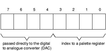
Treatment of logical colours in eight bit per pixel modes
| Bit 7 | goes directly to the top bit of blue |
| Bit 6 | goes directly to the top bit of green |
| Bit 5 | goes directly to the second bit of green |
| Bit 4 | goes directly to the top bit of red |
By default, the palette registers are set to have the following effect:
| Bit 3 | is sent to the second bit of blue |
| Bit 2 | is sent to the second bit of red |
| Bit 1 | is sent to the third bits of blue, green and red |
| Bit 0 | is sent to the fourth bits of blue, green and red |
Hence the palette cannot be used to produce extreme effects upon the colour; it does not have any effect upon the top (most significant) bits of any colour or the second bit of green. It can only control the second bits of blue and red, and the white tint which is obtained by the settings of all three of the third and fourth (least significant) bits.
You can also set the palette using OS_Word 12, and read the current palette using OS_Word 11 and OS_ReadPalette.
VDU 19,5,12,0,0,0 - Set logical colour 5 to be physical colour 12
VDU 20
--
VDU 20 restores the default palette for the current mode. It also resets the default text and graphics background colour to black, and the text and graphics foreground colour to white. The graphics foreground and background actions are set to 0 (overwrite). In 256-colour modes the tints are set to their default values (0 for background tints and &C0 for foreground ones).
Disable screen display
VDU 21
--
VDU 21 prevents the VDU screen drivers performing any of their normal functions until a VDU 6 is issued. Any control sequences sent to the VDU drivers are queued in the usual way. Therefore, sending the character VDU 19 causes the next 5 characters to be treated as parameters for this (ignored) command.
For example, the sequence VDU 22,6 is treated as one whole command in the usual way and not as VDU 22 followed by VDU 6 which would re-enable the VDU drivers.
This command does not prevent characters from being sent to the VDU printer driver (if already enabled by a VDU 2), or any of the other output streams.
You can use OS_Byte 117 to determine whether the VDU driver is currently enabled or disabled.
VDU 22,mode
VDU 22 is used to select a screen mode. The bottom seven bits of the mode parameter are used to select the mode. The modes available in RISC OS depend on the configured monitor type (see *Configure MonitorType on *Configure MonitorType) and the model of computer. Below is a table of all modes provided by RISC OS, which shows:
| Type | Monitor | |
|---|---|---|
| 0 | 50Hz TV standard colour or monochrome monitor | |
| 1 | Multi-frequency monitor | |
| 2 | 64Hz high-resolution monochrome monitor | |
| 3 | 60Hz VGA-type monitor | |
| 4 | Super-VGA-type monitor (not available in RISC OS 2) | |
| 5 | LCD (liquid crystal display) (not available in RISC OS 2) | |
Mode 32 has not been defined.
If an attempt is made to select a mode which is not appropriate to the current monitor type (or OS version), a suitable mode for that monitor is used. For example, an attempt to select mode 23 on a type 0 monitor will result in mode 0 being used.
In 256 colour modes, there are some restrictions on the control of the colours. Only 64 base colours may be selected; 4 levels of tinting turn the base colours into 256 shades. Also, the selection from the colour palette of 4096 shades is only possible in groups of 16.
If 128 is added to the mode number, the so-called shadow bank is used if possible. Any display mode may have several banks of memory available. The number of banks depends on the size of the screen memory (as allocated by *Configure ScreenSize) and the size of the current mode. For example, if 160K is allocated, and 20K is used for the display, eight banks are available.
Usually, bank 1 is used. However, if 128 is added to the mode number, or a *Shadow command has been issued, bank 2 is used after a mode change. Shadow memory can only be used if ScreenSize is at least twice the memory for the required mode.
The other banks may be accessed using OS_Bytes 112 - 113.
The mode command causes the following actions:
If there is not enough configured screen RAM for the mode you have selected, and the application workspace area is not in use, then memory is moved out of the application workspace area to the screen area.
The current screen mode may be read using OS_Byte 135.
The size of the screen in a given mode can be determined by reading VDU variables XWindLimit, YWindLimit, XEigFactor, YEigFactor.
VDU 22,7 - Select Teletext mode
Miscellaneous commands
VDU 23,command,n1,n2,n3,n4,n5,n6,n7,n8
command - the command to perform
n1,n2,n3,n4,n5,n6,n7,n8 - the 8 parameters which follow it
VDU 23 is a multi-purpose command taking nine parameters, of which the first identifies a particular function. Each of the available functions is described below. Eight additional parameters are required in each case, though often most of these are ignored. This enables you to use '|' as shorthand in BASIC VDU statements, as in the example below.
VDU 23,0,10| - These two lines have the same effect
VDU 23,0,10,0,0,0,0,0,0,0
VDU 23,0,action,mode,0,0,0,0,0,0
action - Sets which action to perform
mode - Defines the mode for a given action
| Mode | Effect |
|---|---|
| 0 | sets the screen interlace state to the opposite of the current |
| *TV setting | |
| 1 | sets the screen interlace state to the current *TV setting |
| &80 | turns the screen interlace off |
| &81 | turns the screen interlace on |
If action= 10 or 11, this controls the height of the cursor on the screen and its appearance.
action= 10 mode defines the start line for the cursor and its appearance:
Bits 0 - 4 define the start line (0 being the top)
Bits 5 - 6 define its appearance as follows:
| Bit 6 | Bit 5 | Meaning |
|---|---|---|
| 0 | 0 | Steady |
| 0 | 1 | Off |
| 1 | 0 | Fast flash |
| 1 | 1 | Slow flash |
action = 11 mode defines the end line for the cursor.
The bottom line of the cursor is 7 for 'normal' modes, 9 for standard 'gap' modes, and 19 for mode 7.
VDU 23,0,8,&81| - Turn the screen interlace on
VDU 23,1,mode,0,0,0,0,0,0,0
mode - determines which cursor mode
VDU 23,1 controls the appearance of the text cursor on the screen depending on the value of mode:
| Value | Meaning |
|---|---|
| 0 | stops the cursor appearing |
| 1 | makes the cursor re-appear |
| 2 | makes the cursor steady |
| 3 | makes the cursor flash |
The effect of this call is cancelled when cursor editing occurs. The effect of the previous call is not changed by cursor editing. See also SWI OS_RemoveCursors and SWI OS_RestoreCursors.
VDU 23,1,3| - makes the cursor flash
VDU 23,pattern_no+1,n1,n2,n3,n4,n5,n6,n7,n8
pattern_no+1 - number of pattern to set (1 - 4) plus one
n1,n2,n3,n4,n5,n6,n7,n8 - colour for each row
VDU 23,2 - VDU 23,5 are used to define the four colour patterns:
| VDU 23,2 | sets pattern 1 |
| VDU 23,3 | sets pattern 2 |
| VDU 23,4 | sets pattern 3 |
| VDU 23,5 | sets pattern 4 |
Each of the integers n1 to n8 defines the colours of one row of the pattern, n1 being the top row and n8 being the bottom. For a given parameter, the logical colours of the pixels in each row depend upon the number of colours available in the current screen mode and which pattern mode is used. There are two available pattern modes. The default is the BBC/Master compatible mode. The other is the native RISC OS mode which decodes the values in a simpler fashion. To change between these modes use VDU 23,17,4.
If the bit settings in one of the n parameters is denoted by 76543210, then the logical colours of the pixels in each row (from left to right) are:
| Bits per pixel | No. of colours | No. of pixels in a line | BBC/Master colours | RISC OS colours |
|---|---|---|---|---|
| 1 | 2 | 8 | 7,6,5,4,3,2,1,0 | 0,1,2,3,4,5,6,7 |
| 2 | 4 | 4 | 73, 62, 51, 40 | 10, 32, 54, 76 |
| 4 | 16 | 2 | 7531, 6420 | 3210, 7654 |
| 8 | 256 | 1 | 76543210 | 76543210 |
There are many examples of using these and the VDU 23,12-15 commands to alter ECF functions in the Application Notes.
In any 256 colour mode, each parameter refers to the colour of each line. Use the colour byte as described by VDU 19.
VDU 23,6,n1,n2,n3,n4,n5,n6,n7,n8
n1,n2,n3,n4,n5,n6,n7,n8 - bit pattern for style
VDU 23,6 sets the dot-dash line style used by dotted line PLOT commands (see also VDU 25 - which does the plotting - on VDU 25, and OS_Byte 163 - which sets the dot-dash repeat length - on OS_Byte 163).
Each of the integers n1 to n8 defines eight elements of the line style, n1 being at the start and n8 at the end. The bits in each byte are read from most significant to least significant, each 1-bit indicating a dot and each 0-bit a space. The default is &AAAAAAAA (alternating dots and spaces) with a repeat length of eight (so only n1 is used).
VDU 23,7,extent,direction,movement,0,0,0,0,0
extent - text window or screen
direction - direction to scroll
movement - how much movement
VDU 23,7 allows the current text window or whole screen to be scrolled directly in any direction without moving the cursor. The extent, direction and movement determine the area to be scrolled, the direction of scrolling and the amount of scrolling as follows:
| extent | Effect |
|---|---|
| 0 | scroll the current text window |
| 1 | scroll the entire screen |
| direction | Effect |
| 0 | scroll right |
| 1 | scroll left |
| 2 | scroll down |
| 3 | scroll up |
| 4 | scroll in positive x direction (as set by VDU 23,16) |
| 5 | scroll in negative x direction (as set by VDU 23,16) |
| 6 | scroll in positive y direction (as set by VDU 23,16) |
| 7 | scroll in negative y direction (as set by VDU 23,16) |
| movement | Effect |
| 0 | scroll by one character cell |
| 1 | scroll by one character cell vertically or one byte horizontally |
If movement is 1, the horizontal movement depends on the number of colours in the current mode as follows:
| Number of colours | Number of pixels moved |
|---|---|
| 2 | 8 |
| 4 | 4 |
| 16 | 2 |
| 256 | 1 |
VDU 23,7,0,3,0| - Scroll window up one character
VDU 23,8,base_start,base_end,x1,y1,x2,y2,0,0
base_start - base position of start of block
base_end - base position of end of block
x1, y1, x2, y2 - displacements of block
VDU 23,8 causes a block of the current text window to be cleared to the text background colour. The parameters base_start and base_end indicate base positions relating to the start and end of the block to be cleared respectively:
| Value | Meaning |
|---|---|
| 0 | top left of window |
| 1 | top of cursor column |
| 2 | off top right of window |
| 4 | left end of cursor line |
| 5 | cursor position |
| 6 | off right of cursor line |
| 8 | bottom left of window |
| 9 | bottom of cursor column |
| 10 | off bottom right of window |
References to 'left', 'up' and so on are dependent upon the cursor movement control set by VDU 23,16. 'Off' means 'one character beyond (in the positive x direction)'. The effects of other values, ie. 3, 7 and any number over 10, are undefined.
The parameters x1,y1 and x2,y2 are displacements from the positions specified by the base start and base end; they determine the start and end of the block:
| x1 | Displacement from base start in x direction |
| y1 | Displacement from base start in y direction |
| x2 | Displacement from base end in x direction |
| y2 | Displacement from base end in y direction |
The result is undefined if the absolute values defining the start and end of the block produce values outside the range -128 to 127. If the end point of the block lies before the start point then no clearing takes place.
The action of this command can be viewed as equivalent to moving the text cursor to the start of the block, then printing spaces until the end of the block is reached (but without printing a space at the last position).
VDU 23,8,5,10,0,0,0,0| - Clear from cursor to end of screen
VDU 23,9,duration,0,0,0,0,0,0,0
duration - number of VSyncs
VDU 23,9 sets the flash time for the first flashing colour. The length is determined by the value of duration as follows:
| duration = 0 | sets a steady flash colour 1 |
duration ![[NOT EQUAL]](../symbols/entities/8800.png) 0 0
| sets the duration |
A Vsync is the time between refreshes of the screen display. It varies between display modes and countries. In the UK for modes 0 - 17 it is approximately 1/50th second.
This command is equivalent to OS_Byte 9 (see OS_Byte 9).
VDU 23,9,1| - Set to one Vsync
Set flash time for second flashing colour
VDU 23,10,duration,0,0,0,0,0,0,0
duration - number of VSyncs
VDU 23,10 sets the flash time for the second flashing colour. The length is determined by the value of duration as follows:
| duration = 0 | sets a steady flash colour 2 |
| duration 0
| sets the duration |
This command is equivalent to OS_Byte 10.
VDU 23,10,2| - Set to two VSyncs
VDU 23,11,0,0,0,0,0,0,0,0
--
VDU 23,11 selects the Master 128 compatible pattern mode and causes the four colour patterns to be reset to their defaults for the current screen mode. With the default logical-physical map, these defaults are:
| 1 - Red-orange | 2 - Orange | 3 - Yel-orange | 4 - Cream |
|---|---|---|---|
| 11001100 | 11110000 | 11111111 | 00000011 |
| 00000000 | 00001111 | 00110011 | 00001100 |
| 11001100 | 11110000 | 11111111 | 01000100 |
| 00000000 | 00110011 | 01010101 | 10001000 |
| 1 - Dark grey | 2 - Grey | 3 - Light grey | 4 - Hatching |
|---|---|---|---|
| 10101010 | 11001100 | 11111111 | 00010001 |
| 00000000 | 00110011 | 01010101 | 00100010 |
| 10101010 | 11001100 | 11111111 | 01000100 |
| 00000000 | 00110011 | 01010101 | 10001000 |
| 1 - Red-orange | 2 - Orange | 3 - Yel-orange | 4 - Cream |
|---|---|---|---|
| 2121 | 2121 | 2222 | 2323 |
| 1111 | 1212 | 1212 | 3232 |
| 2121 | 2121 | 2222 | 2323 |
| 1111 | 1212 | 1212 | 3232 |
| 1 - Orange | 2 - Pink | 3 - Yel-green | 4 - Cream |
|---|---|---|---|
| 21 | 61 | 32 | 37 |
| 12 | 16 | 23 | 73 |
| 21 | 61 | 32 | 37 |
| 12 | 16 | 23 | 73 |
| 1 - Grey | 2 - Slate | 3 - Green | 4 - Pink | ||||
|---|---|---|---|---|---|---|---|
| 3F | 00 | 0 | C0 | 4 | C0 | 3B | 00 |
| 40 | 80 | 80 | 40 | ||||
| 80 | 40 | 40 | 80 | ||||
| C0 | 00 | 00 | C0 |
All the patterns repeat after four rows, so only the first four are shown.
VDU 23,11|
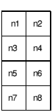
VDU 23,pattern,n1,n2,n3,n4,n5,n6,n7,n8
Define a two by four block of pixels as follows:
The pattern parameter determines which colour pattern is set:
| pattern | Sets colour pattern |
|---|---|
| 12 | 1 |
| 13 | 2 |
| 14 | 3 |
| 15 | 4 |
VDU 23,12-15 are used to define the four colour patterns in a simpler way than that provided by VDU 23,2-5. The limitation is that you can only set a two-by-four pattern of pixels.
The pixels of the top row of the resulting pattern are assigned alternating logical colours n1 and n2, those of the next row have colours n3 and n4 etc.
In any 256 colour mode, the declared use of the parameters does not apply. In this case, each parameter refers to the colour of each line, from 1 to 8. Use the colour byte as described by VDU 19.
To set up the following pattern in mode 1 for colour pattern 1:
| RedYel | 12 |
| WhtRed | 31 |
| BlkRed | 01 |
| WhtYel | 32 |
the required sequence is:
VDU 23,12,1,2,3,1,0,1,3,2
VDU 23,16,x,y,0,0,0,0,0,0
| x | exclusive OR value |
| y | AND value |
VDU 23,16 gives control of the movement of the cursor after a character has been printed. This movement is under the control of a byte of flags. VDU 23,16 replaces the byte by:
The interpretation of the flags is as follows:
| Bit | Value | Effect |
|---|---|---|
| 7 | 0 | Normal. |
| 1 | Undefined. | |
| 6 | 0 | In VDU 5 mode, cursor movements beyond the current edge of the window cause special actions. For example, they generate newlines at the end of the line. |
| 1 | In VDU 5 mode, cursor movements beyond the edge of the window do not cause special actions. This is the most useful mode of VDU 5; used in the Window Manager. | |
| 5 | 0 | Cursor moves in the positive x direction after the character is printed. If this results in the cursor moving beyond the edge of the window, the settings of bits 6, 4 and 0 define the action which is taken. |
| 1 | Cursor does not move after the character is printed. | |
| 4 | 0 | When a cursor movement in the y direction results in the cursor moving beyond the window edge, the window is scrolled if in VDU 4 mode. If in VDU 5 mode, the cursor moves to the opposite edge of the window. |
| 1 | When a cursor movement in the y direction results in the cursor moving beyond the window edge, the cursor is always moved to the opposite edge of the window. | |
| 3 | 0 | x direction is horizontal, y direction is vertical. |
| 1 | x direction is vertical, y direction is horizontal. | |
| 2 | 0 | Positive vertical direction is down. |
| 1 | Positive vertical direction is up. | |
| 1 | 0 | Positive horizontal direction is right. |
| 1 | Positive horizontal direction is left. | |
| 0 | 0 | Disables the scroll-protect option. When printing a character in VDU 4 mode results in the cursor moving beyond the edge of the window, the cursor is instead moved to the negative x edge of the window and one line in the positive y direction. |
| 1 | Enables the scroll protect option. When printing a character in VDU 4 mode results in the cursor moving beyond the edge of the window, a 'pending newline' is generated. It is actually executed just before the next character is printed, provided that it has not been deleted or executed by another cursor control character. For example VDU 127 would cancel it; VDU 9 would execute it. |
VDU 23,16,%00000100,%11111011| - Set vertical direction up
VDU 23,17,action,tint,0,0,0,0,0,0
action - determines which colour is to be set
tint - what the tint is to be set to
VDU 23,17,0-3 is used to set the amount of white tint given to a colour in the 256-colour modes. The action determines which colour's tint is set, as follows:
| action | Colour |
|---|---|
| 0 | sets the tint for the text foreground colour |
| 1 | sets the tint for the text background colour |
| 2 | sets the tint for the graphics foreground colour |
| 3 | sets the tint for the graphics background colour |
The value of the tint is given by the top two bits of the tint parameter:
| tint | Tint effect |
|---|---|
| &00 | Bit 0 and bit 1 clear (darkest) |
| &40 | Bit 0 set and bit 1 clear |
| &80 | Bit 1 set and bit 0 clear |
| &C0 | Bit 0 and bit 1 set (lightest) |
For more details, see the chapter entitled 256-colour modes.
VDU 23,17,0,&C0| - Set the text foreground colour to lightest tint
Choose the patterns used to interpret subsequent VDU 23,2 - 5... calls
VDU 23,17,4,patterns,0,0,0,0,0,0
patterns - which mode of patterns
This command chooses which set of colour patterns are used to interpret subsequent VDU 23,2 - 5... calls, depending on the value of <patterns>:
| patterns | Mode |
|---|---|
| 0 | Use 6502 BBC Micro compatible colour patterns |
| 1 | Use native colour patterns |
VDU 23,17,4,1| - Use native colour patterns
VDU 23,17,5,0,0,0,0,0,0,0
--
This command exchanges the current text foreground and background colours. After the first time it's called, subsequent characters printed are in inverse video. After the second time it's called, subsequent characters printed are of normal appearance.
VDU 23,17,6,x;y;0,0,0
x, y - point coordinates
By default, the alignment of ECF patterns is with the bottom left corner of the screen. This command changes it so that the bottom left pixel of the pattern coincides with the pixel at the specified point.
The origin is restored to the default after a mode change.
OS_SetECFOrigin performs the same action.
VDU 23,17,7,flags,x;y;0,0
flags - what to set the size of
x, y - size in pixels
This command allows changing the size and spacing of VDU 5 characters. They are reset when a mode change occurs. Bit 1 of the flags refers to the size of VDU 5 characters. Bit 2 refers to the spacing between VDU 5 characters. x and y are sizes in pixels.
Sizes of 8x16 and 8x8 are optimised for speed. All other settings are much slower. The spacing settings do not affect the speed. The default size and spacing of VDU 5 characters is 8x8.
VDU 23,17,7,%100,10;8;0,0 - change VDU 5 spacing to 10 pixels
Reserved for future expansion
These calls are provided by the Font Manager for compatibility with earlier operating systems. You must not use them. See the chapter entitled The Font Manager for further details.
This call is provided by the Sprite Manager. See the chapter entitled Sprites for further details.
Reserved for use by application programs.
VDU 23,32-255,n1,n2,n3,n4,n5,n6,n7,n8
32 - 255 - character to define
n1,n2,n3,n4,n5,n6,n7,n8 - definition by row
VDU 23,32 to VDU 23,255 redefine the printable ASCII characters. The redefined character depends on the value of the second parameter. For example, VDU 23,65 redefines the character whose ASCII value is 65, ie capital A. The parameters n1 to n8 are integers representing the eight rows of the character to be redefined, n1 being the top row and n8 the bottom row. Each bit of a value represents one pixel of the corresponding row, with a '1' indicating that the corresponding pixel is to be plotted in the foreground colour and a '0' that it is to be plotted in the background colour (or not at all in the case of VDU 5 mode printing). The most significant bit of the byte corresponds to the left-hand pixel of its row, and the others follow linearly.
Although the delete character (ASCII 127) can be redefined, redefining has no effect as it cannot be displayed.
You can read the pattern for a given character using OS_Word 10.
You should not use this call in programs that might be run under the desktop, as your redefinitions may affect other programs. If you must use this call, ensure you only redefine characters that are normally unused.
Note that the desktop redefines some characters for its own use, and you must not redefine these yourself. To determine which characters are normally unused, view the entire system font under the desktop (the !Chars application is ideal for this):
VDU 23,65,&AA,&55,&AA,&55,&AA,&55,&AA,&55 - redefine 'A'
VDU 24,x1;y1;x2;y2;
x1, y1, x2, y2 - coordinates of window
VDU 24 allows the user to define a graphics window. Any graphics objects which are drawn (including VDU 5 mode and fancy-font characters) and which lie outside this window are clipped to the edges of the window. The four parameters define the left, bottom, right and top boundaries of the window respectively, relative to the current graphics origin (the bottom left of the screen, by default). The window which you are defining must lie within the screen boundaries, otherwise the command is ignored.
The coordinates are inclusive - that is, the points you specify lie within the window.
Use OS_ReadVduVariables to discover the size of the current graphics window.
The following example shows how to derive (in this instance, xsize) the size of a window in OS units
DIM blk% 12
VduExt_XEigFactor% = 4
VduExt_XWindLimit% = 11
blk%!0 = VduExt_XEigFactor%
blk%!4 = VduExt_XWindLimit%
blk%!8 = -1
SYS "OS_ReadVduVariables", blk%, blk%
xeigfactor% = blk%!0
xwindlimit% = blk%!4: REM in pixels
xwindsize%  = (xwindlimit% + 1) << xeigfactor%: REM in OS units
VDU 25,type,x;y;
type - what kind of plot to perform
x, y - where to plot
VDU 25 is a multi-purpose graphics plotting command. The first parameter defines a particular function. The other parameters are the x coordinate and the y coordinate. They are relative either to the current graphics origin, or to the last point visited, depending on the value of type.
The bottom three bits of type determine the manner in which the plot is to be performed. Thus (type AND 7) has the following effects:
The remaining bits of type determine the action to be performed. The value given here is added to the 0 - 7 range above to get all the possible combinations. The value here is the decimal starting value:
| Value | Effect |
|---|---|
| 0 | Solid line including both end points |
| 8 | Solid line excluding the final point |
| 16 | Dotted line including both end points, pattern restarted |
| 24 | Dotted line excluding the final point, pattern restarted |
| 32 | Solid line excluding the initial point |
| 40 | Solid line excluding both end points |
| 48 | Dotted line excluding the initial point, pattern continued |
| 56 | Dotted line excluding both end points, pattern continued |
| 64 | Point Plot |
| 72 | Horizontal line fill (left and right) to non-background |
| 80 | Triangle fill |
| 88 | Horizontal line fill (right only) to background |
| 96 | Rectangle fill |
| 104 | Horizontal line fill (left and right) to foreground |
| 112 | Parallelogram fill |
| 120 | Horizontal line fill (right only) to non-foreground |
| 128 | Flood to non-background |
| 136 | Flood to foreground |
| 144 | Circle outline |
| 152 | Circle fill |
| 160 | Circular arc |
| 168 | Segment |
| 176 | Sector |
| 184 | Block copy/move * |
| 192 | Ellipse outline |
| 200 | Ellipse fill |
| 208 | Font printing - see the chapter entitled The Font Manager |
| 216 | Reserved for Acorn Expansion |
| 224 | Reserved for Acorn Expansion |
| 232 | Sprite Plot - see the chapter on sprites |
| 240 | Reserved for User programs |
| 248 | Reserved for User programs |
| The eight values in the range 184 - 191, which perform a block copy/move, have the following meanings: | |
| Value | Effect |
|---|---|
| 184 | Move relative |
| 185 | Relative rectangle move |
| 186 | Relative rectangle copy |
| 187 | Relative rectangle copy |
| 188 | Move absolute |
| 189 | Absolute rectangle move |
| 190 | Absolute rectangle copy |
| 191 | Absolute rectangle copy |
Some of the objects require several points to be specified in order to define the shape completely. The last plot does the actual drawing. The sequences of moves and draws required for each type are:
| Shape | Sequence of moves |
|---|---|
| Line | Move to one endpoint. Plot line to other endpoint. |
| Triangle | Move to first vertex. Move to second vertex. Plot triangle to last vertex. |
| Rectangle | Move to one corner. Plot rectangle to diagonally- opposite corner. |
| Parallelogram | Move to first corner. Move to second corner. Plot parallelogram to third corner. The fourth corner is derived from the other three, and is opposite the second one. |
| Circle | Move to centre. Plot circle to point on the circumference. |
| Arc, segment, sector | Move to centre of circle. Move to start of arc. Plot to a point on the line from the centre to the end of the arc. Arcs, etc, are always drawn counter-clockwise. |
| Block copy/move | Move to one corner of source rectangle. Move to diagonally-opposite corner of source rectangle. Plot block copy/move to lower left of destination rectangle. |
| Ellipse | Move to centre. Move to intersection of ellipse circumference and centre's y coordinate. Plot ellipse to highest or lowest point on the ellipse. |
VDU 25,69,100;200; - plot point absolute
Restore default windows
VDU 26
--
VDU 26 causes the text and graphics windows to be reset to their default states, ie both become the full screen. In addition, the command resets the graphics origin to (0,0), moves the graphics cursor to (0,0) and moves the text cursor to its home position. Hardware scrolling of the text window is initiated.
No operation
VDU 27
--
This VDU has no effect
VDU 28,x1,y1,x2,y2
x1 - left-most x column
y1 - bottom-most y row
x2 - right-most x column
y2 - top-most y row
VDU 28 defines (or redefines) a text window. The parameters are integers specifying the boundary of the window as above.
If the command attempts to define a window which extends outside the screen boundaries, has x1 greater than x2, or has y1 less than y2, it will have no effect. The smallest possible window is one character.
You can read the size of the current text window using OS_ReadVduVariables.
VDU 29,x;y;
x, y - where the origin is to be set
VDU 29 defines the point specified as the origin to be used for all subsequent graphics output using VDU 25 commands, and for the graphics window defined by VDU 24. The parameters are the two pairs of bytes specifying the absolute x and y coordinates of the new origin.
You can read the position of the current origin using OS_ReadVduVariables.
VDU 30
--
VDU 30 moves the text cursor to its 'home' position. This is normally the top left of the window but may be changed (using VDU 23,16). In VDU 5 mode the graphics cursor is moved instead. It may have an offset of up to (character size -1) pixels out of the corner along one or both of the axes to allow for the height or width of the character depending on the direction of character printing.
VDU 31,x,y
x, y - text position to move to
VDU 31 moves the text cursor to a specified x and y coordinate on the screen. The parameters x and y are the column and row numbers.
In VDU 4 mode, x and y are given relative to the text 'home' position which is at (0,0). If the position lies outside the text window, nothing happens, unless the scroll protect option is enabled and the x coordinate is just beyond the positive x edge of the window. In this case, the text cursor is moved to position (x-1,y) and a pending newline is generated.
In VDU 5 mode the graphics cursor is moved to its 'home' position plus (x character spacing × x) pixels in the positive x direction, plus (y character spacing × y) pixels in the positive y direction. It is possible to move the cursor outside the graphics window in VDU 5 mode.
You can read the position of the text cursor using OS_Byte 134.
VDU 31,10,5
VDU 127
--
Unless the previous use of VDU 23,16 indicates that no cursor movement is to take place after character printing, the cursor is moved backwards as if by VDU 8. Then the character under the cursor is deleted by overprinting it with a space (in VDU 4 mode) or a solid block of graphics background colour (in VDU 5 mode). These space and solid block characters are selected from the 'hard' (rather than the 'soft') font, so redefining these characters will not change the results.
R1 = &46 (reason code)
R2 = mode number
R3 = monitor type
All registers preserved (do not claim)
This call is made whenever a mode change has taken place. It is made for the benefit of modules which may want to re-read some VDU variables to keep a consistent view of the world. Neither RISC OS 2 nor RISC OS 3 (version 3.00) pass the mode number and monitor type.
You should not claim this service call; there is nothing a module can do to prevent the mode change from taking place.
R1 = &4D (reason code)
R2 = selected mode (before possible translation)
R1 preserved
R2 preserved
This is the normal action for a module which does not want to interfere
R1 = 0 (service claimed)
R0 = 0
This implies that the module does not want the mode change to take place, and has taken an alternative action.
R1 = 0 (service claimed)
R0 pointer to an error block
This implies that the module does not want the mode change to take place, and wishes to return the error pointed to by R0.
R1 preserved
R2 = new mode
This implies that the module wants to substitute a mode for the specified mode. This is not a very good way of doing it, as other modules further down the chain will be offered the service with this new mode. The Service_ModeTranslation mechanism described below should be used by modules providing new monitor types.
This service call is now of little use, as better alternatives are available.
R1 = &50 (reason code)
R2 = mode number that information is requested for
R3 = monitor type (or -1 for don't care)
All registers preserved (if not claimed)
If claimed:
R1 = 0
R2 preserved
R3 = pointer to VIDC list
R4 = pointer to workspace list
This service call is issued when information is needed on a particular mode: for example on a mode change, or when mode variables are read. In RISC OS it is possible to load modules which provide additional screen modes and additional monitor types; such modules must claim this call if they recognise the passed mode and monitor type, and return the information.
Under RISC OS 3 (version 3.10) and later this service call is no longer issued for mode/monitor combinations that RISC OS itself already supports.
If writing a module providing soft modes, the mode number you use must fit this scheme:
| Modes | Use |
|---|---|
| 0 - 63 | Reserved for use by RISC OS |
| 64 - 95 | Reserved for third party applications |
| 96 - 127 | Reserved for user defined modes |
Mode numbers in the range 64 - 95 are allocated by Acorn.
Likewise, monitor types are allocated by Acorn. There are no monitor types pre-reserved for general use by users.
The returned VIDC list consists of a series of words. The first word specifies the format of the list, so this can be altered to cope with new hardware such as new versions of VIDC. There are currently two different formats. The first is:
| Offset | Value |
|---|---|
| 0 | 0 (format of list) |
| 4 | VIDC base mode |
| 8 | VIDC parameter |
| 12 | VIDC parameter |
| ... | ... |
| n | -1 |
The VIDC base mode is the number of an existing operating system screen mode which is used to determine the values of VIDC registers not explicitly mentioned in the list. The VIDC parameters are in the form that would be written to the hardware: ie the top 6 bits specify which register is programmed, and the remainder specify the value to be programmed in that register.
However, bits 6 and 7 of the control register should be set to 0, as these will be modified by RISC OS to take the configured sync and the *TV interlace setting into account. Similarly the vertical parameters for border start, display start, display end and border end are modified by RISC OS to take the *TV vertical offset into account.
VIDC parameters below &80000000 are ignored, since these correspond to palette registers (determined by the workspace base mode) and sound registers (not part of the display system).
On older machines, the VIDC clock is fixed at 24MHz, and the pixel rate is only determined by VIDC's internal dividers, as specified in bits 0 and 1 of the Control Register (VIDC address &E0). Newer machines have extra hardware to allow the selection of different VIDC clocks, and to determine the polarity of the sync lines. VIDC uses its clock together with a set of internal dividers to provide a range of pixel rates. For example, the A540 hardware provides the following pixel rates:
The second format of VIDC list was introduced to support these features. It is similar to format 0 (see above), but adds extended parameters:
| Offset | Value |
|---|---|
| 0 | 1 (format of list) |
| 4 | VIDC base mode |
| 8 | VIDC parameter |
| 12 | VIDC parameter |
| ... | |
| n | -1 |
| n+4 | Extended parameter |
| n+8 | Extended parameter |
| ... | |
| m | -1 |
Extended parameters are of the form:
(0 << 24) + (pixel rate in kHz)
This will override the settings of bits 0 and 1 of a Control Register specifier in the main body of the list. If no pixel rate is specified, then the VIDC clock is set to 24MHz, and the settings of the divider in the Control Register are used as normal.
If the pixel rate specified is not achievable with the hardware on the machine, the nearest available pixel rate is used. When specifying a pixel rate for a hi-res-mono display, the pixel rate specified should be the actual pixel rate divided by 4, ie 24000 not 96000.
or:
(1 << 24) + (sync polarity)
where the sync polarity is defined as follows:
| Bits | Meaning |
|---|---|
| 0 | 0  HSYNC PVE (AS ON A STANDARD ARCHIMEDES)_ 1 HSync -ve HSYNC PVE (AS ON A STANDARD ARCHIMEDES)_ 1 HSync -ve
|
| 1 | 0 VSYNC PVE (AS ON A STANDARD ARCHIMEDES)_ 1 VSync -ve
|
| 2 - 23 | reserved; must be zero |
| If no sync polarity is specified, a default of 0 is used (ie the same as a normal Archimedes). | |
or, from RISC OS 3 (version 3.10) onwards:
(2 << 24) + (true VIDC clock rate in kHz)
This is intended to be used in systems where the clock rate fed to VIDC is under the control of some external device, rather than being selected by the clock select latch. (For example, on the portable machine, the LCD ASIC feeds either 8MHz or 16MHz into VIDC when LCD modes are selected).
The values programmed into the clock select latch and the VIDC divider are still determined either from the control register specifier or a pixel rate specifier assuming the same range of clock speeds as on the A540; but the VIDC clock rate specifier is used to determine the video memory rate, which in turn determines the VIDC FIFO Request Pointer values (bits 4 and 5 of the VIDC control register). The VIDC clock rate specifier is also stored in VDU variable VIDCClockSpeed (&AC), which is used by the SoundDMA module to determine the VIDC Sound Frequency Register value.
All values are words in the workspace list; its format is:
| Offset | Value |
|---|---|
| 0 | 0 (indicates format of list) |
| 4 | Workspace base mode |
| 8 | Mode variable index |
| 12 | Mode variable value |
| 16 | Mode variable index |
| 20 | Mode variable value |
| ... | ... |
| n | -1 |
The workspace base mode is the number of an existing operating system screen mode which is used to determine the values of mode variables not explicitly mentioned in the list. The mode variable indices are the same as for
SWI OS_ReadModeVariable.
Modules can provide their own palette programming routines, including setting of the default palette, by claiming PaletteV. For more details see PaletteV on PaletteV, and Service_ModeChanging on Service_ModeChanging. This feature is not available under RISC OS 2, nor under RISC OS 3 (version 3.00); for these you should choose a workspace base mode which has an appropriate palette already set.
When the service is received, the module should check that R2 contains a mode
that it knows about and that R3 holds a monitor type that is suitable for that mode. If not, the service should be passed on. If R3 holds -1 then the MOS is making a general enquiry about that mode (eg to determine the attributes of a sprite defined in that mode) so the module should only check R2.
Note that it is possible for a mode to have two or more different sets of VIDC parameters for different monitor types, but the workspace parameters must be the same, as the mode number is used as an identifier in sprites and in calls such as OS_ReadModeVariable.
R1 = &51 (reason code)
R2 = mode number that requires translation
R3 = monitor type
All registers preserved (if not claimed)
If claimed:
R1 = 0
R2 = substitute mode
R3 preserved
This service is offered during a call to OS_CheckModeValid or a screen mode change, if the selected mode is not available with the current monitor type (this having been ascertained by offering Service_ModeExtension) and the monitor type is not one known to the MOS (ie not in the range 0 - 3 for RISC OS 2.00, or 0 - 4 otherwise).
If the monitor type passed in R3 is known to the module, then the module should discover what the attributes of the mode in R2 are (by calling OS_ReadModeVariable) and then choose a mode which is suitable for this monitor type and is closest in attributes to the selected mode. This mode number should be returned in R2.
R1 = &76 (reason code)
R2 = monitor lead ID (see below)
If monitor lead ID is recognised, then the module should set:
R1 = 0 (claim service)
R3 = default screen mode number to use on this type of monitor
R4 = monitor type number to use (as used in *Configure MonitorType)
R5 = sync type to use on this type of monitor (0 SEPARATE SYNCS_ 1 composite sync)
All other registers must be preserved.
If the monitor lead ID is not recognised, the module should preserve all registers.
This service call is issued if SWI OS_ReadSysInfo is called with R0=1 and any of the configured Mode, MonitorType or Sync are set to Auto.
The monitor connector provides 4 ID pins, ID0-ID3, each of which may be connected to 0v, +5v or to the Hsync pin. The monitor lead ID represents the state of these 4 ID pins by 4 2-bit fields, with ID0 in bits 0 and 1, ID1 in bits 2 and 3, ID2 in bits 4 and 5, and ID3 in bits 6 and 7. The meaning of each field is as follows:
| Value | Meaning |
|---|---|
| 0 | ID pin is tied to 0v |
| 1 | ID pin is tied to +5v |
| 2 | ID pin is tied to Hsync |
| 3 | Indeterminate - either the state is fluctuating, or the machine is not capable of reading the ID |
If your module recognises the monitor lead ID, you should claim the service call and return a monitor type, sync type, and default screen mode to use. For example, the Portable module (which is only present on portables) recognises the ID 1111 returned when no lead is connected, and sets the monitor type to 5 (LCD), the sync to 0, and the default mode to 27.
If the service is not claimed, then RISC OS checks the monitor lead ID against the following list of recognised IDs, and adopts these defaults:
| ID0 | ID1 | ID2 | ID3 | Monitor type | Sync type | Default mode |
|---|---|---|---|---|---|---|
| H | 1 | 1 | X | 0 (TV standard) | 1 (composite) | 12 |
| 1 | 1 | H | X | 1 (Multisync) | 1 (composite) | 27 |
| 1 | 0 | 1 | X | 3 (Mono VGA) | 0 (separate) | 27 |
| 0 | 1 | 1 | X | 3 (Colour VGA) | 0 (separate) | 27 |
| 0 | 1 | 0 | X | 4 (Super VGA) | 0 (separate) | 27 |
where the values in the ID columns have the following meanings:
| Value | Meaning |
|---|---|
| 0 | ID pin must be tied to 0v |
| 1 | ID pin must be tied to +5v |
| H | ID pin must be tied to Hsync |
| X | Value of ID pin is immaterial |
If RISC OS still does not recognise the monitor lead ID, it assumes it to be a TV standard monitor, and uses those settings (ie composite sync, default mode 12).
This service call is not issued by RISC OS 2. Furthermore, older machines such as the A300 and A400 series, and the A3000, cannot detect the sense of the monitor lead IDs.
R1 = &89 (reason code)
R2 = mode number
R3 = monitor type
All registers preserved (do not claim)
This service call is issued during a mode change, after Service_PreReset has been issued and a mode change is inevitable, but before it has actually happened. It is intended for use by modules that wish to claim PaletteV on particular combinations of mode number and monitor type. They should claim or release PaletteV depending on whether or not their module recognises the combination of mode number and monitor type. This allows modules providing extended palettes and the like to intercept RISC OS's palette programming.
For example, it is used in this way by the Portable module when an LCD screen mode is selected.
For more details, see the documentation of PaletteV on PaletteV.
This service call is not issued by RISC OS 2, nor by RISC OS 3 (version 3.00).
R0 = 9 (reason code)
R1 = new duration to write
R0 = preserved
R1 = duration before being overwritten
R2 = corrupted
Interrupt status is not altered
Fast interrupts are enabled
Processor is in SVC mode
Not defined
This call sets the duration of the first flash colour.
Flashing colours are displayed as a sequence of two alternating colours. By default, each colour is displayed for 25 video frames at a time, which is approximately 0.5 seconds for 50Hz screen modes in the UK. This command allows you to alter the duration for which the first colour is displayed as follows:
| Value | Meaning |
|---|---|
| 0 | Set an infinite duration (first colour constantly displayed) |
| n | Set the duration to n video frames (approximately n/50 seconds) |
This variable may also be set using VDU 23,9. It may be read (but not set) by OS_Byte 195.
ByteV
Write duration of second flash colour
R0 = 10
R1 = duration to write
R0 preserved
R1 = duration before being overwritten
R2 corrupted
Interrupt status is not altered
Fast interrupts are enabled
Processor is in SVC mode
Not defined
This call sets the duration for the second flash colour. See OS_Byte 9 for an explanation.
This variable may also be set using VDU 23,10. It may be read (but not set) by OS_Byte 194.
R0 = 19
R0 preserved
R1, R2 corrupted
Interrupt status is not altered
Fast interrupts are enabled
Processor is in SVC mode
Not defined
The video display frame is drawn approximately fifty times a second for most screen modes in the UK. This call synchronises a software routine with the signal produced when the video output reaches the bottom of the displayed area of the picture (ie the start of the border).
From this time until the next frame starts to be displayed, you can redraw the screen.
It is possible to have more than this time by drawing from top to bottom, or setting a timer to wait until video output has passed the place on the screen you want to redraw.
If even this is not enough time to produce a flicker-free update of the screen, you should consider using more than one bank of screen memory and switching between them (using OS_Bytes 112-113 for example).
ByteV
R0 = 20
R0 preserved
R1, R2 corrupted
Interrupt status is not altered
Fast interrupts are enabled
Processor is in SVC mode
Not defined
The shape of the character displayed when printing ASCII codes 32-255 may be redefined using the VDU 23,32-255 commands. Any such changes remain in force until the next hard reset. This command may be used to restore the default character definitions for ASCII codes in the range 32 - 127.
Note that you should anyway not redefine characters in the range 32 - 127, since they all have standard meanings which should be preserved for use in applications such as word processors.
See OS_Byte 25 for details on how to restore the other codes or how to restore a smaller selected group.
ByteV
Reset group of font definitions
R0 = 25
R1 = group to restore
R0 preserved
R1, R2 corrupted
Interrupt status is not altered
Fast interrupts are enabled
Processor is in SVC mode
Not defined
All ASCII characters between 32 and 255 may be redefined using the VDU 23 command. This call restores all or a particular group of characters to their default settings according to R1, as follows:
| Value | Range of characters to restore |
|---|---|
| 0 | 32-255 |
| 1 | 32-63 |
| 2 | 64-95 |
| 3 | 96-127 |
| 4 | 128-159 |
| 5 | 160-191 |
| 6 | 192-223 |
| 7 | 224-255 |
R0 = 106
R1 = pointer shape and linkage flag
R0 preserved
R1 = shape and linkage flag before being overwritten
R2 corrupted
Interrupt status is not altered
Fast interrupts are enabled
Processor is in SVC mode
Not defined
You can define four 'pointer buffers' using OS_Word 21, each holding a different shape definition for the mouse pointer. This call allows you to select one of these definitions for future use, or to turn off the pointer depending on the bottom seven bits of R1:
| Value | Meaning |
|---|---|
| 0 | Turn off current pointer |
| 1-4 | Select given pointer |
If a pointer is selected it can be linked to the mouse so the mouse drives it, depending on bit seven of R1 as follows:
| Value | Meaning |
|---|---|
| &00 | Link pointer to mouse |
| &80 | Pointer unlinked |
For example, a value in R1 of &03 selects pointer three and links it to the mouse, and a value of &82 selects pointer two but leaves it unlinked.
ByteV
R0 = 112
R1 = bank number
R0 preserved
R1 = previous bank number
R2 corrupted
Interrupt status is not altered
Fast interrupts are enabled
Processor is in SVC mode
Not defined
This call selects the bank of screen memory which is to be used by the VDU drivers according to R1, as follows:
| Value | Bank |
|---|---|
| 0 | Default for the current screen mode (1 or 2) |
| n | Select bank 'n' |
The maximum value for 'n' is (TotalScreenSize)/(ModeSize), where TotalScreenSize is the amount actually present in screen memory and ModeSize is the size of the current mode. For example, in mode 0, a 20K mode with 160K set aside for the screen makes eight banks available, so 8 is the maximum value for 'n'.
The default bank for a non-shadow mode is bank 1; for a shadow mode it is bank 2. OS_Byte 250 may be used to read the bank number without writing it.
ByteV
Write display hardware screen bank
R0 = 113
R1 = bank number
R0 preserved
R1 = value before being overwritten
R2 corrupted
Interrupt status is not altered
Fast interrupts are enabled
Processor is in SVC mode
Not defined
This call selects the bank of screen memory which is to be used by the display hardware according to R1:
| Value | Bank |
|---|---|
| 0 | Default for the current screen mode |
| n | Select bank n |
The bank may be read (but not set) using OS_Byte 251.
ByteV
Write shadow/non-shadow state
R0 = 114
R1 = shadow state
R0 preserved
R1 = value before being overwritten
R2 corrupted
Interrupt status is not altered
Fast interrupts are enabled
Processor is in SVC mode
Not defined
This call determines whether future MODE commands will be forced into the shadow state, depending on R1:
| Value | Meaning |
|---|---|
| 0 | Modes will be shadow |
| 1 | Modes will be non-shadow |
Shadow state requires twice the amount of RAM than the equivalent non-shadow mode since two copies of the screen are stored in memory. OS_Bytes 112 and 113 control the use of the banks.
To select a shadow state temporarily when in non-shadow mode, you can use the MODE 128+n convention. Future MODE commands will not be influenced by this.
R0 = 117
R0 preserved
R1 = status byte
Interrupt status is not altered
Fast interrupts are enabled
Processor is in SVC mode
Not defined
This call returns the content of the VDU status byte. This byte gives information on the way in which characters are output according to their bit settings:
| Bit | Status when set |
|---|---|
| 0 | Printer output enabled by VDU 2 |
| 1 | Unused |
| 2 | Paged scrolling selected by VDU 14 |
| 3 | Text window in force (ie software scrolling) |
| 4 | In a shadow mode |
| 5 | In VDU 5 mode |
| 6 | Cursor editing in progress |
| 7 | Screen disabled with VDU 21 |
None
ByteV
R0 = 134
R0 preserved
R1 = position in x direction
R2 = position in y direction
Interrupt status is not altered
Fast interrupts are enabled
Processor is in SVC mode
Not defined
This call returns the current text cursor position unless cursor editing is in progress, in which case the position returned is that of the input cursor. OS_Byte 165 reads the position of the output cursor irrespective of cursor editing mode.
Text is printed at x positions 0 to n-1, where 'n' is the number of characters per line in the current text window. Therefore, the value obtained is normally in this range. However, if there is a pending newline (see VDU 23,16), a position of 'n' will be returned.
ByteV
R0 = 135
R0 preserved
R1 = ASCII value of character (0 if unreadable)
R2 = screen mode
Interrupt status is not altered
Fast interrupts are enabled
Processor is in SVC mode
Not defined
This call returns the screen mode and the ASCII code of the character at the text cursor position. If cursor editing is in progress, it returns the character code returned by the character at the input cursor position (ie the character that would be copied as input the next time Copy is pressed).
Note that the screen mode does not have bit 7 set, even if it is a shadow mode.
None
ByteV
R0 = 144
R1 = vertical screen shift (as a signed 8 bit number)
R2 = interlace flag
R0 preserved
R1 = previous vertical screen shift
R2 = previous interlace flag
Interrupt status is not altered
Fast interrupts are enabled
Processor is in SVC mode
Not defined
This call specifies the vertical screen alignment and interlace options after the next mode change. R1 sets the vertical offset. R2 turns interlace on and off as follows:
| Value | Meaning |
|---|---|
| 0 | Interlace on |
| 1 | Interlace off |
This is equivalent to *TV, which is described in this chapter.
None
ByteV
R0 = 160
R1 = VDU variable number (0-15)
R0 preserved
R1 = value of variable
R2 = value of next variable (R1 on entry + 1)
Interrupt status is not altered
Fast interrupts are enabled
Processor is in SVC mode
Not defined
The VDU driver uses a number of locations in RAM to store transient information. This call allows some of these locations to be examined. Note that the variables are not necessarily stored in the order implied by the value of R1 on entry. However, the relationship between R1 and the variable read is guaranteed to remain the same for all versions of RISC OS.
| Value | Location |
|---|---|
| 0 | LSB of graphics window left column (ic) |
| 1 | MSB of graphics window left column (ic) |
| 2 | LSB of graphics window bottom row (ic) |
| 3 | MSB of graphics window bottom row (ic) |
| 4 | LSB of graphics window right column (ic) |
| 5 | MSB of graphics window right column (ic) |
| 6 | LSB of graphics window top row (ic) |
| 7 | MSB of graphics window top row (ic) |
| 8 | Text window left column |
| 9 | Text window bottom row |
| 10 | Text window right column |
| 11 | Text window top row |
| 12 | LSB of graphics origin x coordinate (ec) |
| 13 | MSB of graphics origin x coordinate (ec) |
| 14 | LSB of graphics origin y coordinate (ec) |
| 15 | MSB of graphics origin y coordinate (ec) |
This OS_Byte is provided mainly for compatibility with the BBC/Master 128. You can read many more of the VDU variables using OS_ReadVduVariables and OS_ReadModeVariable.
ByteV
R0 = 163
R1 = 242
R2 = dot-dash repeat length or action code
R0 preserved
R1 = status, or preserved
R2 = status, or preserved
Interrupt status is not altered
Fast interrupts are enabled
Processor is in SVC mode
Not defined
This call is a general purpose one reserved for Acorn applications. The only value of R1 which is guaranteed to perform a useful function is 242. The type of action depends on the value of R2:
| Value | Meaning |
|---|---|
| 0 | Set default dot-dash pattern and length |
| 1-64 | Set dot-dash line repeat length to the value given |
| 65 | Return status information |
| 66 | Return information on the current sprite |
The status information is returned in R1 and R2 as follows:
| R1 bits | Meaning |
|---|---|
| Bit 7 = 1 | Sprites are always active |
| Bit 6 = 1 | Flood fill is always active |
| Bits 0-5 | Current dot dash line repeat length (0 means 64) |
| R2 bits | Meaning |
|---|---|
| Bits 0-31 | Current size of the system sprite area in bytes. |
The information on the current sprite is returned in R1 and R2 as follows:
None
ByteV
R0 = 165
R0 preserved
R1 = position in x direction
R2 = position in y direction
Interrupt status is not altered
Fast interrupts are enabled
Processor is in SVC mode
Not defined
This call returns the position of the output cursor, even while cursor editing is in progress.
ByteV
R0 = 193
R1 = 0 to read or new duration to write
R2 = 255 to read or 0 to write
R preserved
R1 = duration before being overwritten
R2 corrupted
Interrupt status is not altered
Fast interrupts are enabled
Processor is in SVC mode
Not defined
The duration stored is changed by being masked with R2 and then exclusive ORd with R1: ie ((duration AND R2) XOR R1). This means that R2 controls which bits are changed and R1 supplies the new bits.
This call accesses the location used as a count-down timer for the flashing colours. The location is loaded with the count for the first colour and decremented at a VSync rate, providing that the current flash period is not infinite. When it reaches zero, the colours are swapped and the counter is loaded with the duration of the second colour.
ByteV
Read duration of second colour
R0 = 194
R1 = 0
R2 = 255
R0 preserved
R1 = duration
R2 corrupted
Interrupt status is not altered
Fast interrupts are enabled
Processor is in SVC mode
Not defined
This call reads the duration of the second colour, as set by OS_Byte 10.
The value read is only a record of the current duration. You must not attempt to use this call to write the value; doing so would merely change the stored value, without making any actual change. To change the duration you must instead call OS_Byte 10. This call is only included for backwards compatibility.
ByteV
Read duration of first colour
R0 = 195
R1 = 0
R2 = 255
R0 preserved
R1 = duration
R2 corrupted
Interrupt status is not altered
Fast interrupts are enabled
Processor is in SVC mode
Not defined
This command will read the location that has been set by OS_Byte 9.
The value read is only a record of the current duration. You must not attempt to use this call to write the value; doing so would merely change the stored value, without making any actual change. To change the duration you must instead call OS_Byte 9. This call is only included for backwards compatibility.
R0 = 211
R1 = 0 to read or new channel to write
R2 = 255 to read or 0 to write
R0 preserved
R1 = channel before being overwritten
R2 = bell sound information (see OS_Byte 212)
Interrupt status is not altered
Fast interrupts are enabled
Processor is in SVC mode
Not defined
The channel stored is changed by being masked with R2 and then exclusive ORd with R1: ie ((channel AND R2) XOR R1). This means that R2 controls which bits are changed and R1 supplies the new bits.
The bell (VDU 7) sound is output on channel 1 by default. This call provides a means of determining the current channel, or changing it if required.
ByteV
R0 = 212
R1 = 0 to read or new volume to write
R2 = 255 to read or 0 to write
R0 preserved
R1 = volume before being overwritten
R2 = bell frequency (see OS_Byte 213)
Interrupt status is not altered
Fast interrupts are enabled
Processor is in SVC mode
Not defined
The volume stored is changed by being masked with R2 and then exclusive ORd with R1: ie ((volume AND R2) XOR R1). This means that R2 controls which bits are changed and R1 supplies the new bits.
This allows you to read or set the volume of the sound used to make the Ctrl-G bell sound. Values for the amplitude are in the range &80 (loudest) to &F8 (softest) in steps of &08. The default setting depends on the *Configure Loud/Quiet setting (&90/&D0 respectively).
ByteV
R0 = 213
R1 = 0 to read or new frequency to write (in range 0 - 255)
R2 = 255 to read or 0 to write
R0 preserved
R1 = frequency before being overwritten
R2 = bell duration (see OS_Byte 214)
Interrupt status is not altered
Fast interrupts are enabled
Processor is in SVC mode
Not defined
The frequency stored is changed by being masked with R2 and then exclusive ORd with R1: ie ((frequency AND R2) XOR R1). This means that R2 controls which bits are changed and R1 supplies the new bits.
This call provides a means of reading or changing the frequency associated with the bell sound. The default value is 100, and it has the same interpretation as the *Sound command.
The frequency must be an old-style BBC frequency: ie in the range 0 - 255.
ByteV
R0 = 214
R1 = 0 to read or new duration to write
R2 = 255 to read or 0 to write
R0 preserved
R1 = duration before being overwritten
R2 corrupted
Interrupt status is not altered
Fast interrupts are enabled
Processor is in SVC mode
Not defined
The duration stored is changed by being masked with R2 and then exclusive ORd with R1: ie ((duration AND R2) XOR R1). This means that R2 controls which bits are changed and R1 supplies the new bits.
This call provides a means of reading or changing the duration of the bell sound. The default value is 6, and the unit is 20ths of a second.
R0 = 217
R1 = 0 to read or new count to write
R2 = 255 to read or 0 to write
R0 preserved
R1 = count before being overwritten
R2 corrupted
Interrupt status is not altered
Fast interrupts are enabled
Processor is in SVC mode
Not defined
The count stored is changed by being masked with R2 and then exclusive ORd with R1: ie ((count AND R2) XOR R1). This means that R2 controls which bits are changed and R1 supplies the new bits.
In the paged output mode, the display is prevented from scrolling (awaiting the depression of Shift) when approximately 75% of the height of the current text window has been scrolled. The number of lines printed since the last page halt is maintained in the location accessed by this call and it may be either read or changed (normally to 0 before requesting user input).
If you are using OS_Word 0 or OS_ReadLine to perform the input, this call is made automatically. OS_Word 0 is provided for compatibility only and should not be used.
None
ByteV
R0 = 218
R1 = 0 to read or new count to write
R2 = 255 to read or 0 to write
R0 preserved
R1 = count before being overwritten
R2 corrupted
Interrupt status is not altered
Fast interrupts are enabled
Processor is in SVC mode
Not defined
The count stored is changed by being masked with R2 and then exclusive ORd with R1: ie ((count AND R2) XOR R1). This means that R2 controls which bits are changed and R1 supplies the new bits.
This call affects the count of the number of characters which remain to be passed to the VDU driver in order to complete the current VDU sequence. The value is (minus the number of bytes left), and is held in 2's complement notation (eg. &FF means one byte to go). The call may be used to read the value or to change it (normally to zero, which has the effect of abandoning an incomplete VDU command).
You can use this call when an escape condition is acknowledged. This prevents the first few characters of an error message from being 'swallowed' by an incomplete VDU sequence.
None
ByteV
R0 = 250
R1 = 0
R2 = 255
R0 preserved
R1 = screen bank used by VDU drivers
R2 = display screen bank (see OS_Byte 251)
Interrupt status is not altered
Fast interrupts are enabled
Processor is in SVC mode
Not defined
This call reads the current VDU driver screen bank number, as set by OS_Byte 112.
The value read is only a record of the current VDU driver screen bank. You must not attempt to use this call to write the value; doing so would merely change the stored value, without making any actual change. To change the duration you must instead call OS_Byte 112. This call is only included for backwards compatibility.
ByteV
Read display screen bank number
R0 = 251
R1 = 0
R2 = 255
R0 preserved
R1 = screen bank used by the display
R2 corrupted
Interrupt status is not altered
Fast interrupts are enabled
Processor is in SVC mode
Not defined
This call reads the current display screen bank number, as set by OS_Byte 113.
The value read is only a record of the current display screen bank. You must not attempt to use this call to write the value; doing so would merely change the stored value, without making any actual change. To change the duration you must instead call OS_Byte 113. This call is only included for backwards compatibility.
R0 = 9 (reason code)
R1 = pointer to parameter block
R0 preserved
R1 preserved:
Interrupt status is not altered
Fast interrupts are enabled
Processor is in SVC mode
Not defined
This call determines the logical colour of the pixel at given coordinates on the graphics screen. In 256 colour modes this call ignores the tint, and returns a value in the range 0 - 63. Consequently you should always use OS_ReadPoint in preference, since it returns both the logical colour and tint.
If the colour is returned as &FF then either:
This call is provided for backwards compatibility only.
WordV
R0 = 10
R1 = pointer to parameter block
R0 preserved
R1 preserved:
Interrupt status is not altered
Fast interrupts are enabled
Processor is in SVC mode
Not defined
The characters displayed in all modes other than Teletext mode are defined as an eight-by-eight matrix of dots. This call enables you to read the definition for a specified ASCII code. However, the definitions returned for ASCII codes 0 to 31 and 127 (ie the non-printing characters) are not meaningful apart from the following characters:
| Value | Information returned |
|---|---|
| 2 | ECF pattern 1 (in native mode) |
| 3 | ECF pattern 2 (in native mode) |
| 4 | ECF pattern 3 (in native mode) |
| 5 | ECF pattern 4 (in native mode) |
| 6 | Dot-dash pattern |
Bits set in each row of the character definition are displayed in the current text foreground colour; bits clear in each row are displayed in the current text background colour. In VDU 5 mode, bits which are set are plotted in the graphics foreground colour and action; bits which are clear are not plotted at all.
None
WordV
R0 = 11
R1 = pointer to parameter block
R0 preserved
R1 preserved:
Interrupt status is not altered
Fast interrupts are enabled
Processor is in SVC mode
Not defined
This call allows you to determine the physical colour associated with a particular logical colour. The call can only return one of the colours associated with a flashing colour. To read the full information about a logical colour's palette entry, or to read the border and pointer palettes, you should use OS_ReadPalette. The OS_Word is provided for compatibility only.
WordV
R0 = 12
R1 = pointer to parameter block
R0, R1 preserved
Interrupt status is not altered
Fast interrupts are enabled
Processor is in SVC mode
Not defined
This call allows you to change the physical colour associated with a particular logical colour. It duplicates the function of VDU 19 command. However, the OS_Word call is faster and may be used in interrupt routines. The five bytes of the parameter block are equivalent to the five parameters l,p,r,g,b described in the section on VDU 19 (see VDU 19).
None
WordV
R0 = 13
R1 = pointer to parameter block
R0 preserved
R1 preserved:
Interrupt status is not altered
Fast interrupts are enabled
Processor is in SVC mode
Not defined
All the coordinates are in external form. You can read points visited before the previous one (and many other VDU variables) using OS_ReadVduVariables. The OS_Word is provided for compatibility only.
WordV
R0 = 21
R1 = pointer to parameter block
R0, R1 preserved
Interrupts are enabled (in RISC OS 2, the interrupt status is not altered)
Fast interrupts are enabled
Processor is in SVC mode
Not defined
You can define four shapes. These are numbered one to four and may be selected using OS_Byte 106.
As the pointer is always displayed in 2 bits per pixel (four pixels per byte), and the maximum width in bytes is 8, the maximum width is 32 pixels.
The ActiveX and ActiveY entries give the distance of the cursor 'hot spot' from the top left corner of the pointer. If these are zero, then positioning the pointer at coordinates (x, y) will move the top left corner to that position. Suppose the shape was a cross-hair 9 pixels in each direction; then making ActiveX and ActiveY (5,5) would position the hot-spot at the centre of the cross.
The data for the shape is pointed to by R1+6-R1+9. This data table contains the information for each row, from top to bottom, and the data within each row is given from left to right. Each byte contains the colours for four pixels. Bits 0,1 hold the colour number for the left-most pixel, bits 6,7 the colour for the right-most pixel. (So the pixels are displayed in reverse order to the order in which the byte would be written down.)
Colour zero is always transparent (ie the screen information shows through pixels in this colour). The other three colours may be set independently of any other colours on the screen using VDU 19 or the equivalent OS_Word.
However, note that colour two should be used with caution in defining pointer shapes, as it does not work correctly on high-resolution mono screens.
WordV
R0 = 21
R1 = pointer to parameter block
| R1 + 0 = 1 (sub-reason code) | |
| R1 + 1 = LSB of left coordinate | All treated as signed 16-bit values, relative to screen origin at the time the command is issued |
| R1 + 2 = MSB of left coordinate | |
| R1 + 3 = LSB of bottom coordinate | |
| R1 + 4 = MSB of bottom coordinate | |
| R1 + 5 = LSB of right coordinate | |
| R1 + 6 = MSB of right coordinate | |
| R1 + 7 = LSB of top coordinate | |
| R1 + 8 = MSB of top coordinate |
R0, R1 preserved
Interrupt status is not altered
Fast interrupts are enabled
Processor is in SVC mode
Not defined
The coordinates should be given as signed 16-bit values relative to the graphics origin at the time the command is issued.
If (left > right) or (bottom > top) then the command is ignored.
An infinite box can be obtained by setting:
| left | = | &8000 | (-32768) |
| bottom | = | &8000 | (-32768) |
| right | = | &7FFF | (32767) |
| top | = | &7FFF | (32767) |
If the current mouse position is outside the box, it is homed to the nearest point inside the box. The buffer is not flushed, but any buffered coordinates will be moved inside the bounding box when they are read.
When the mode changes, the box is set to the size of the screen.
None
WordV
R0 = 21
R1 = pointer to parameter block
R0, R1 preserved
Interrupt status is not altered
Fast interrupts are enabled
Processor is in SVC mode
Not defined
The multipliers control the ratio between the movement of the mouse and the change in the coordinates of the mouse. The higher each value, the greater the amount the pointer moves (if linked to the mouse) for a given movement of the mouse.
The multipliers should both be given as signed eight-bit values. By specifying negative values (eg. 255 for -1), you can make the pointer move in the opposite direction from usual.
Both multipliers default to the configured MouseStep value. The factory defaults for this have varied between versions of RISC OS:
| RISC OS version | MouseStep | Mouse movement per screen width |
|---|---|---|
| 2 | 1 | 15cm |
| 3 (version 3.00) | 2 | 7.5cm |
| 3 (version 3.10) | 3 | 5cm |
None
WordV
R0 = (reason code)
R1 = pointer to parameter block
R0, R1 preserved
Interrupt status is not altered
Fast interrupts are enabled
Processor is in SVC mode
Not defined
The new values for the x and y positions of the mouse are given as two signed 16-bit values. If the new position lies outside the bounding box of the mouse, this command will be ignored.
Note that this call sets the position of the mouse rather than the pointer. If the mouse and pointer are not linked, the position of the pointer on the screen is left unchanged.
None
WordV
R0 = 21
R1 = pointer to parameter block
R0 preserved
R1 preserved:
Interrupt status is not altered
Fast interrupts are enabled
Processor is in SVC mode
Not defined
This call will read the position of the mouse at the time of the call. That is, it will not read the position from the mouse buffer.
Care should be taken when reading this position, as the buffer positions may be significantly out of step.
With RISC OS 2.00 this call generates an undefined instruction trap due to a stack mismatch. This was fixed in RISC OS 2.01.
None
WordV
R0 = 21 (reason code)
R1 = pointer to parameter block
R0, R1 preserved
Interrupt status is not altered
Fast interrupts are enabled
Processor is in SVC mode
Not defined
The new values for the x and y positions of the pointer are given as two signed 16-bit values.
Note that this call sets the position of the pointer rather than the mouse. If the mouse and pointer are linked, then the pointer position will be updated with the mouse position on the next VSync interrupt.
None
WordV
R0 = 21
R1 = pointer to parameter block
| R1+0 = 6 |
R0 preserved
R1 preserved:
Interrupt status is not altered
Fast interrupts are enabled
Processor is in SVC mode
Not defined
This call will read the position of the pointer. If the mouse and pointer are not linked, then this call reads the position that the pointer was last set to.
If they are linked, then the pointer is updated from the unbuffered mouse position every VSync.
None
R0 = 22
R1 = pointer to parameter block
R0, R1 preserved
Interrupt status is not altered
Fast interrupts are enabled
Processor is in SVC mode
Not defined
This routine sets up a new screen base address. It is given as the offset from the address of the base of the screen buffer to the start of the screen display. This address can be used as the area of the buffer which is to be updated, ie written to by the VDU drivers, or the area which is to be displayed by the hardware, or both, depending on the bits of the first byte in the parameter block:
| Bit 0 | Used by VDU drivers |
| Bit 1 | Displayed by hardware |
This allows multiple screens to be used. For example, in mode 12 two copies of the screen can be kept. One of these can be updated whilst the other is being displayed using the following parameter blocks:
| R1 + 0 | Contains 2 | Displayed |
| R1 + 1-R1+4 | Contains &00 | |
| R1 + 0 | Contains 1 | Updated |
| R1 + 1-R1+4 | Contains &14000 |
Then the two screens can be swapped over (at VSync) by changing over the addresses so that smooth animation is obtained.
The configured ScreenSize determines the amount of RAM initially set aside for the screen. This can subsequently change, for example if you drag the screen memory bar in the Task Manager, or call OS_ChangeDynamicArea. You can read the current amount set aside for the screen by reading the VDU variable TotalScreenSize; and you can read the amount needed for a single screen by reading the mode variable ScreenSize.
A slightly simpler way of achieving bank switching is to use OS_Bytes 112-113. With these, you only have to specify the bank number, not the actual offset.
WordV
--
R0 = mouse x coordinate
R1 = mouse y coordinate
R2 = mouse buttons
R3 = time of button change
Interrupts are disabled
Fast interrupts are enabled
Processor is in SVC mode
SWI cannot be re-entered as interrupts are disabled
OS_Mouse reads from the mouse buffer the mouse x and y positions as values between -32768 and 32767. Unless the graphics origin has been changed, the coordinates will lie within the mouse bounding box, which initially defaults to the screen area. The call also returns buttons currently pressed as a value in the range 0-7:
| Bit | Meaning when set |
|---|---|
| 0 | Right button down |
| 1 | Middle button down |
| 2 | Left button down |
If there is no entry in the mouse buffer, the current status is returned. R3 gives the time the entry was buffered, or the current time if it is not a buffered reading. It uses the monotonic timer (see OS_ReadMonotonicTime).
MouseV
R0 = logical colour
R1 = type of colour
R2 = setting of first flashing colour
R3 = setting of second flashing colour
Interrupt status is undefined
Fast interrupts are enabled
Processor is in SVC mode
SWI is not re-entrant
OS_ReadPalette reads the setting of a particular colour that is sent to the hardware. R1 selects whether the normal colour, border colour or pointer colour is read as follows:
| Value | Meaning |
|---|---|
| 16 | Read normal colour |
| 24 | Read border colour |
| 25 | Read pointer colour |
The settings for the first flash colour and second flash colour are returned in R2 and R3 respectively. If these are identical then the colour is a steady, non-flashing one. The value contained in each of these is interpreted as follows:
| Bits | Meaning |
|---|---|
| 0-6 | Value showing how colour was programmed |
| 7 | Supremacy bit |
| 8-15 | Amount of red |
| 16-23 | Amount of green |
| 24-31 | Amount of blue |
The bottom byte (bits 0-7) returns the value of the second parameter to the VDU 19 command which defines the palette (bit 7 is the supremacy bit). For example:
| Value | Meaning |
|---|---|
| 0-15 | Actual colour (BBC compatible) |
| 16 | Defined by giving amounts of red, green and blue |
| 17-18 | Flashing colour defined by giving amounts of red, green and blue |
RISC OS 3 (version 3.10) and later versions no longer return values in the range 0 - 15. Instead they always return 16 for BBC colours 0 - 7, and 17 and 18 for BBC flashing colours 8 - 15.
None
None
R0 = pointer to input block
R1 = pointer to output block
R0, R1 preserved
Interrupt status is undefined
Fast interrupts are enabled
Processor is in SVC mode
SWI is not re-entrant
OS_ReadVduVariables reads in a series of VDU variables and places them in sequence into a block of memory. The input block consists of a sequence of words. Each word is the number of the variable to be read. A value of -1 terminates the list. The value of each variable is put as a word into the output block, any invalid variables being entered as zero. The output block has no terminator. Both blocks must be word-aligned.
The possible variable numbers are the same as for OS_ReadModeVariable (see OS_ReadModeVariable) with the following additions:
| Name | No. | Meaning |
|---|---|---|
| GWLCol | 128 | Left-hand column of the graphics window (ic) |
| GWBRow | 129 | Bottom row of the graphics window (ic) |
| GWRCol | 130 | Right-hand column of the graphics window (ic) |
| GWTRow | 131 | Top row of the graphics window (ic) |
| TWLCol | 132 | Left-hand column of the text window |
| TWBRow | 133 | Bottom row of the text window |
| TWRCol | 134 | Right-hand column of the text window |
| TWTRow | 135 | Top row of the text window |
| OrgX | 136 | x coordinate of the graphics origin (ec) |
| OrgY | 137 | Y coordinate of the graphics origin (ec) |
| GCsX | 138 | x coordinate of the graphics cursor (ec) |
| GCsY | 139 | Y coordinate of the graphics cursor (ec) |
| OlderCsX | 140 | x coordinate of oldest graphics cursor (ic) |
| OlderCsY | 141 | Y coordinate of oldest graphics cursor (ic) |
| OldCsX | 142 | x coordinate of previous graphics cursor (ic) |
| OldCsY | 143 | Y coordinate of previous graphics cursor (ic) |
| GCsIX | 144 | x coordinate of graphics cursor (ic) |
| GCsIY | 145 | Y coordinate of graphics cursor (ic) |
| NewPtX | 146 | x coordinate of new point (ic) |
| NewPtY | 147 | Y coordinate of new point (ic) |
| ScreenStart | 148 | Address of the start of screen used by VDU drivers |
| DisplayStart | 149 | Address of the start of screen used by display hardware |
| TotalScreenSize | 150 | Amount of memory currently allocated to the screen |
| GPLFMD | 151 | GCOL action for foreground colour |
| GPLBMD | 152 | GCOL action for background colour |
| GFCOL | 153 | Graphics foreground colour |
| GBCOL | 154 | Graphics background colour |
| TForeCol | 155 | Text foreground colour |
| TBackCol | 156 | Text background colour |
| GFTint | 157 | Tint for graphics foreground colour |
| GBTint | 158 | Tint for graphics background colour |
| TFTint | 159 | Tint for text foreground colour |
| TBTint | 160 | Tint for text background colour |
| MaxMode | 161 | Highest mode number available |
| GCharSizeX | 162 | x size of VDU 5 chars (in pixels) |
| GCharSizeY | 163 | Y size of VDU 5 chars (in pixels) |
| GCharSpaceX | 164 | x spacing of VDU 5 chars (in pixels) |
| GCharSpaceY | 165 | Y spacing of VDU 5 chars (in pixels) |
| HLineAddr | 166 | Address of fast line-draw routine |
| TCharSizeX | 167 | x size of VDU 4 chars (in pixels) |
| TCharSizeY | 168 | Y size of VDU 4 chars (in pixels) |
| TCharSpaceX | 169 | x spacing of VDU 4 chars (in pixels) |
| TCharSpaceY | 170 | Y spacing of VDU 4 chars (in pixels) |
| GcolOraEorAddr | 171 | Address of colour blocks for current GCOLs |
| VIDCClockSpeed | 172 | VIDC clock speed in kHz (eg 24000 24 MHz) - not available in RISC OS 2.00
|
| WindowWidth | 256 | Characters that will fit on a row of the text window without a newline being generated |
| WindowHeight | 257 | Rows that will fit in the text window without scrolling it |
| R0 = | left x coordinate of end of line | ||||||||||||||||
| R1 = | y coordinate of line | ||||||||||||||||
| R2 = | right x coordinate of end of line | ||||||||||||||||
| R3 = | 0 | plot with no action (ie do nothing) | |||||||||||||||
| 1 | plot using foreground colour and action | ||||||||||||||||
| 2 | invert current screen colour | ||||||||||||||||
| 3 | plot using background colour and action | ||||||||||||||||
 4 4
| pointer to colour block (on 64-byte boundary):
| ||||||||||||||||
| R14 = return address | |||||||||||||||||
| Must be entered in SVC mode | |||||||||||||||||
| All registers are preserved on exit | |||||||||||||||||
All coordinates are in terms of pixels from the bottom left of the screen. The line is clipped to the graphics window, and is plotted using the colour action specified by R3. The caller must have previously called OS_RemoveCursors and call OS_RestoreCursors afterwards.
n+&00-n+&3F is a colour block for the foreground colour + action
n+&40-n+&7F is a colour block for the background colour + action
n+&80-n+&BF is a colour block for the background colour with store action
Each colour block is as described above. These are updated whenever a GCOL or TINT is issued or the ECF origin is changed. They are intended for programs which want to access screen memory directly and have access to the current colour/action settings.
R0 = x coordinate
R1 = y coordinate
Interrupt status is undefined
Fast interrupts are enabled
Processor is in SVC mode
SWI is not re-entrant
The coordinates passed are in external units and are relative to the current graphics origin.
OS_ReadPoint takes a point and returns its colour in R2 and its tint setting (amount of white, in the range 0-255) in R3. R4 returns the following:
| Value | Meaning |
|---|---|
| 0 | Point on the screen |
| -1 | Point off the screen (R2 = -1 also) |
See VDU 19 for a description of colour and tint values.
None
None
R0 = screen mode, or -1 for current mode
R1 = variable number
R0, R1 preserved
R2 = value of variable
the C flag is set if variable or mode numbers were invalid
Interrupt status is undefined
Fast interrupts are enabled
Processor is in SVC mode
SWI is not re-entrant
OS_ReadModeVariable allows you to read information about a particular screen mode without having to change into that mode. The possible variable numbers are given below:
| Name | Number | Meaning | ||
|---|---|---|---|---|
| ModeFlags | 0 | The bits of the result have the following meanings: | ||
| Bit 0 | = 0 | graphics mode | ||
| = 1 | non-graphics mode | |||
| Bit 1 | = 0 | non-Teletext mode | ||
| = 1 | Teletext mode | |||
| Bit 2 | = 0 | non-gap mode | ||
| = 1 | gap mode | |||
| Bit 3 | = 0 | non-gap mode | ||
| = 1 | 'BBC' gap mode (eg modes 3 and 6) | |||
| Bit 4 | = 0 | not Hi-resolution mono mode | ||
| = 1 | Hi-resolution mono mode | |||
| Bit 5 | = 0 | VDU characters are normal height | ||
| = 1 | VDU characters are double height | |||
| Bit 6 | = 0 | hardware scroll used | ||
| = 1 | Maximum column number for printing text ie number of columns-1. | |||
| ScrBRow | 2 | Maximum row number for printing text ie number of rows-1. | ||
| NColour | 3 | Maximum logical colour ie either 1, 3, 15 or 63 (not 255). | ||
| XEigFactor | 4 | This indicates the number of bits by which an X coordinate must be shifted right to convert to screen pixels. Thus if this value is n, then one screen pixel corresponds to 2n external coordinates in the X direction. | ||
| YEigFactor | 5 | This indicates the number of bits by which a Y coordinate must be shifted right to convert to screen pixels. Thus if this value is n, then one screen pixel corresponds to 2n external coordinates in the Y direction. | ||
| LineLength | 6 | Offset in bytes from a point on a pixel row to the same point on the pixel row below. | ||
| On current hardware this is the same as (characters per row) × (bits per pixel) × (pixel width of character) / 8; for example, in mode 15 it is 80×8×8/8, or 640. You must not assume this will always be the case. | ||||
| ScreenSize | 7 | Number of bytes one screen buffer occupies. This must be a multiple of 256 bytes. | ||
| YShftFactor | 8 | Scaling factor for start address of a screen row. This variable is kept for compatibility reasons and should not be used. | ||
| Log2BPP | 9 | LOG base 2 of the number of bits per pixel. | ||
| Log2BPC | 10 | LOG base 2 of the number of bytes per character. It is in fact the LOG base 2 of the number of bytes per character divided by eight. So in mode 0, for example, it is LOG base 2 of (8/8), or 0. In mode 15 it is LOG base 2 of (64/8), or 3. It would be exactly the same as Log2BPP, except for the 'double pixel' modes. | ||
| XWindLimit | 11 | Number of x pixels on screen-1. | ||
| YWindLimit | 12 | Number of y pixels on screen-1. | ||
-
-
Interrupt status is undefined
Fast interrupts are enabled
Processor is in SVC mode
SWI is not re-entrant
OS_RemoveCursors removes the cursors (output and copy, if active) from the screen, saving the old state (their positions, flash rate etc.) on an internal stack so that it may be recovered later. This instruction must always be balanced later by a OS_RestoreCursors to restore the cursor again.
This call is provided only for routines that need direct screen access.
Note that routines that directly access the screen may need to run in SVC mode if the routines are to work with hardware scrolled screens, which may straddle the logical-physical memory boundary at 32MByte. If the routines do not need to work with hardware scrolled screens, then USR mode is adequate.
None
-
-
Interrupt status is undefined
Fast interrupts are enabled
Processor is in SVC mode
SWI is not re-entrant
OS_RestoreCursors restores the cursor state previously saved on the internal stack using OS_RemoveCursors.
This call is provided only for routines that need direct screen access.
None
R0 = mode number to check
if C flag = 0 then mode is valid:
Interrupt status is undefined
Fast interrupts are enabled
Processor is in SVC mode
SWI is not re-entrant
OS_CheckModeValid determines whether you can change to a given mode and return with the carry bit appropriately set. If the mode you're checking is not available on the current type of monitor, then R1 will contain the mode that will be used if an attempt is made to select the mode which you are checking, using VDU 22. If there is insufficient memory or the call is unable to determine an alternative for another reason, then -2 will be returned.
If this call returns that there is insufficient memory for the required mode, then it can be borrowed from other areas of the machine. See the chapter entitled Memory Management for details.
Note: For all versions of RISC OS, this call returns -2 to indicate there is 'insufficient memory' if the currently allocated amount of screen memory is too little for the specified mode. It does not take into account whether the area could grow.
None
None
R0 = plot command code
R1 = x coordinate
R2 = y coordinate
R0 - R2 corrupted
Interrupt status is undefined
Fast interrupts are enabled
Processor is in SVC mode
SWI is not re-entrant
This call is equivalent to a VDU 25 command. However, it is much more efficient as only one call is required (instead of six calls to OS_WriteC). The call goes directly to the VDU drivers unless spooling has been turned on, redirection has been turned on or if WrchV has been claimed.
None
WrchV
R0 = x coordinate
R1 = y coordinate
R0, R1 preserved
Interrupt status is undefined
Fast interrupts are enabled
Processor is in SVC mode
SWI is not re-entrant
By default, the alignment of ECF patterns is with the bottom left corner of the screen. This command makes the bottom left of the pattern coincide with the bottom left of the specified point.
The origin is restored to the default after a mode change.
VDU 23,17,6 performs the same action.
None
None
Read system information
R0 = reason code
R0 - R4 depend on reason code
Interrupt status is not altered
Fast interrupts are enabled
Processor is in SVC mode
SWI is re-entrant
This call reads various system information, depending on the reason code passed in R0. Current reason codes are:
|
R0 |
Meaning |
Page |
|---|---|---|
|
0 |
Read configured screen size in bytes | |
|
1 |
Read configured Mode, MonitorType, and Sync | |
|
2 |
Read presence of chips, and unique machine ID | |
|
3 |
Read features mask for 82C710 chip family |
None
None
R0 = 0 (reason code)
R0 = amount of configured screen memory, in bytes
This call reads the configured screen size in bytes (which is that used after the next hard reset). See *Configure ScreenSize.
R0 = 1 (reason code)
R0 = configured Mode/WimpMode
R1 = configured MonitorType
R2 = configured Sync
This call reads the configured Mode/WimpMode (which, from RISC OS 3 onwards, are identical), MonitorType, and Sync. See *Configure Mode, *Configure WimpMode, *Configure MonitorType, and *Configure Sync.
If any of the above have been configured to 'Auto', then the appropriate value for the attached monitor is returned.
This call is not available under RISC OS 2.
Read the presence of various chips, and unique machine ID
R0 = 2 (reason code)
absent present (type 1) absent present absent present (type 1)This call checks for the presence of various chips, returning flags. It also reads the unique machine ID if a suitable chip is fitted to the computer; if none is, then the call returns an ID of zero.
Flag values not shown above are reserved for future hardware platforms that may have versions of the chips which are not backwards compatible.
This call is not available under RISC OS 2.
R0 = 3 (reason code)
R0 = 82C710/82C711 basic features mask (see below)
R1 = 82C710/82C711 extra features mask (reserved for upwards compatible additional functionality)
R2-R4 reserved for future expansion
The 82C710 family of chips are composed of several sub-units. Future chips in the family may have some sub-units which are incompatible with earlier versions, while leaving the functionality of other sub-units unchanged. This call returns a features mask, sub-fields within which show the 'compatibility level' of each sub-unit. Differing values of a sub-field indicate incompatible versions of the corresponding sub-unit. A sub-field of zero indicates that the sub-unit is not present. The values for the 82C710 and 82C711 are:
| Bits | Sub-unit | 82C710 | 82C711 |
|---|---|---|---|
| 0 - 3 | IDE hard disc interface | 1 | 1 |
| 4 - 7 | floppy disc interface | 1 | 1 |
| 8 - 11 | parallel port | 1 | 1 |
| 12 - 15 | 1st serial port | 1 | 1 |
| 16 - 19 | 2nd serial port | 0 | 1 |
| 20 - 23 | chip configuration | 1 | 2 |
| 24 - 31 | reserved | 0 | 0 |
(The 710 only supports a single serial port. Obviously the 710 and 711 have differing chip configurations.)
If a sub-unit gains additional backwards-compatible functionality in future versions of the chip, this will be indicated by having bits set in the value returned in R1. Information on extra sub-units will be accommodated in the remaining bits of R0, or in R2-R4.
This call is not available under RISC OS 2, nor under RISC OS 3 (version 3.00).
| R0 = | 0 | disable changed box calculations |
| 1 | enable changed box calculations | |
| 2 | reset changed box to null rectangle | |
| -1 | read changed box information |
R0 = previous enable state in bit 0 (0 for disabled, 1 for enabled)
R1 = pointer to a fixed block of 5 words, containing the following info:
The (R1+4) to (R1+16) values are only valid if the change box calculations were in an enabled state immediately after the call; otherwise they are undefined.
Interrupt status is undefined
Fast interrupts are enabled
Processor is in SVC mode
SWI is not re-entrant
This call checks which areas of the screen have changed over calls to the VDU drivers. When this feature is enabled, RISC OS maintains the coordinates of a rectangle which completely encloses any areas that have changed since the last time the rectangle was reset.
This is particularly useful for applications which switch output to sprites, and then want to repaint the sprite onto the screen after performing VDU operations on the sprite. The application can make significant speed improvements by only repainting the section of the sprite which corresponds to the changed box.
All coordinates are measured in pixels from the bottom left of the screen. If a module provides extensions to the VDU drivers, it should read the address of this block on initialisation, and update the coordinates as appropriate. If an exact calculation of which areas have been modified is difficult, then the module should extend the rectangle to include the whole of the graphics window (or indeed the whole screen, if the operation can affect areas outside the graphics window).
The disable/enable flag at offset 0 in the block is for information only - it must not be modified directly, as RISC OS holds the master copy of this flag.
Changed box calculations are disabled on a mode change. However, the disable/enable state and the coordinates of the rectangle form part of the information held in save areas when output is switched between the screen and sprites.
None
None
R0 = flags:
| bits 0 - 3 | graphics plotting action (see below) |
| bit 4 | set ALTER BACKGROUND_ CLEAR alter foreground
|
| bit 5 | set R1 = PATTERN DATA_ CLEAR R1 = colour number
|
| bits 6 - 31 | reserved (must be zero) |
--
Interrupt status is undefined
Fast interrupts are enabled
Processor is in SVC mode
Not defined
This call sets the foreground or background graphics colours.
You can obtain the colour number to use from ColourTrans_ReturnColourNumber. You can supply an eight word pattern block to use giant ECFs instead of solid colours. With this call you can define a giant pattern for both the foreground and background colours, whereas the VDU drivers only allow you to set a single pattern for both (see VDU 23,2-5 on VDU 23,2-5).
The graphics plotting action passed in bits 0 - 3 of R0 is as follows:
| Value | Action |
|---|---|
| 0 | Overwrite colour on screen with colour |
| 1 | OR colour on screen with colour |
| 2 | AND colour on screen with colour |
| 3 | exclusive OR colour on screen with colour |
| 4 | Invert colour on screen |
| 5 | Leave colour on screen unchanged |
| 6 | AND colour on screen with (NOT colour) |
| 7 | OR colour on screen with (NOT colour) |
| 8 - 15 | As 0 to 7, but background colour is transparent |
None
*Configure Loud
None
*Configure Loud sets the configured volume for the beep to be loud.
The change takes effect on the next reset.
*Configure Quiet
None
*Configure Mode screen_mode|Auto
| screen_mode | the display mode that the computer should use after a power-on or hard reset, and when entering or leaving the desktop |
| Auto | automatic setting of appropriate mode using monitor lead |
*Configure Mode sets the configured screen mode used by the machine when it is first switched on, or after a hard reset, and when entering or leaving the desktop. It is identical to the command *Configure WimpMode; the two commands alter the same value in CMOS RAM.
You can also set a value of Auto (not available in RISC OS 2). More recent Acorn computers can sense the type of monitor lead connected, and hence set an appropriate mode. If no lead can be sensed, either because none is present or because the computer is of an older design, the mode defaults to mode 12.
Under RISC OS 2, this command only sets the configured screen mode used for the command line; *Configure WimpMode sets the configured screen mode used for the Desktop.
*Configure Mode 27 selects VGA mode with 16 colours
*Configure WimpMode, VDU 22
None
None
*Configure MonitorType n|Auto
| n | 0 to 5 | Auto | automatic sensing of monitor type using monitor lead |
*Configure MonitorType sets the configured monitor type that is connected to the computer. The values of n correspond to the following monitors:
| n | Monitor | |
|---|---|---|
| 0 | 50Hz TV standard colour or monochrome monitor | |
| 1 | Multiscan monitor | |
| 2 | Hi-resolution 64Hz monochrome monitor | |
| 3 | VGA-type monitor | |
| 4 | Super-VGA-type monitor | (not available in RISC OS 2) |
| 5 | LCD (liquid crystal display) | (only available on portables) |
You can also set a value of Auto (not available in RISC OS 2). More recent Acorn computers can sense the type of monitor lead connected, and hence set the monitor type. If no lead can be sensed, either because none is present or because the computer is of an older design, the monitor type defaults to 0, save for portables, which default to 5 (an LCD).
You can also configure the monitor type by holding down the corresponding key from the numeric keypad while the computer is switched on.
VDU 22
None
None
Sets the configured value for how fast the pointer moves as you move the mouse
*Configure MouseStep n
| n | a number between 1 and 127 |
*Configure MouseStep sets the configured value for how fast the pointer moves as you move the mouse. Useful values of n are 1, 2 or 3 for slow, medium or fast, respectively.
The mouse position is moved by n coordinates for each movement of the mouse. Although values up to 127 are accepted, anything above 6 is impractical because the step is too large.
You can also use OS_Word 21,2 to set the mouse step dynamically.
*Configure MouseStep 3 select a fast speed
None
None
Sets the configured scrolling so the screen does not scroll upwards at the end of a line
*Configure NoScroll
None
*Configure NoScroll sets the configured scrolling so that a newline is not generated when a character is printed at the end of a line. The default value is Scroll.
When printing a character in VDU 4 mode results in the cursor moving beyond the edge of the window, a 'pending newline' is generated. It is actually executed just before the next character is printed, provided that it has not been deleted or executed by another cursor control character. For example VDU 127 would cancel it; VDU 9 would execute it.
Refer to VDU 23,16 for a lengthier description of NoScroll, and for details of how to set this option dynamically.
*Configure Scroll
None
None
Sets the configured volume for the beep to half its loudest volume.
*Configure Quiet
None
*Configure Quiet sets the configured volume for the beep to half its loudest volume.
The change takes effect on the next reset.
*Configure Loud
None
Sets the configured amount of memory reserved for screen display
*Configure ScreenSize mK|n
| mK | number of kilobytes of memory reserved |
| n | number of pages of memory reserved; n  127 127
|
*Configure ScreenSize sets the configured amount of memory reserved for screen display. The default value is 80Kbytes on a 0.5Mbyte machine, and 160Kbytes for all other machines.
You can also use OS_ChangeDynamicArea to alter the screen memory allocation dynamically. For more information, refer to the chapter entitled Memory Management.
You cannot configure more than 480Kbytes of screen memory, due to limitations in the MEMC1 and MEMC1a memory controllers.
*Configure ScreenSize 160K reserve 160Kbytes for screen display
None
None
Sets the configured scrolling so the screen scrolls upwards at the end of a line
*Configure Scroll
None
*Configure Scroll sets the configured scrolling so that a newline is generated automatically when a character is printed at the end of a line. This is the default value.
When printing a character in VDU 4 mode results in the cursor moving beyond the edge of the window, the cursor is instead moved to the negative x edge of the window and one line in the positive y direction.
Refer to VDU 23,16 for a lengthier description of Scroll, and for details of how to set dynamically this option.
*Configure NoScroll
None
None
Sets the configured type of synchronisation for vertical sync output
*Configure Sync 0|1|Auto
| 0 | vertical sync |
| 1 | composite sync |
| Auto | automatic sensing of required synchronisation type using monitor lead |
*Configure Sync sets the configured type of synchronisation that is provided on the vertical sync output of the video connector. This may be vertical sync (parameter of 0) or composite sync (parameter of 1).
You can also set a value of Auto (not available in RISC OS 2). More recent Acorn computers can sense the type of monitor lead connected, and hence set the required synchronisation type. If no lead can be sensed, either because none is present or because the computer is of an older design, the synchronisation type defaults to 1 (composite sync).
*Configure Sync 1
None
None
None
Sets the configured vertical screen alignment and screen interlace
*Configure TV [vert_align[[,]interlace]]
| vert_align | adjusts the vertical screen alignment 0 to 3 lines up (values of 0-3 respectively), or 1 to 4 lines down (values of 255-252 respectively) |
| interlace | switches screen interlace on (with a value of 0), or off (with a value of 1) |
*Configure TV sets the configured vertical screen alignment and screen interlace. The default values are 0,1 (no vertical alignment offset and interlace off).
*Configure TV 0,1 the default value
*TV
None
None
Sets which bank of screen memory is used on subsequent mode changes
*Shadow [0|1]
0 or 1 or nothing
*Shadow sets which bank of screen memory is used on subsequent changes to the screen mode. It controls two banks of screen memory: the normal bank (bank 1, known as the non-shadow bank), and an alternate bank (bank 2, known as the shadow bank).
If you give either no parameter, or a parameter of 0, the shadow bank is used on the next mode change. If you give a parameter of 1, the non-shadow bank is used on the next mode change.
For the shadow bank to be used, there must be at least double the memory for the selected screen mode available in the screen area of memory. For example, to use shadow memory in screen mode 8 (a mode which requires 40Kbytes), at least 80Kbytes of screen memory must be available.
This command is provided for backwards compatibility only, since there is no useful benefit in using twice as much screen memory.
*Shadow 1
*Configure ScreenSize
None
None
*TV [vert_align[[,]interlace]]
| vert_align | adjusts the vertical screen alignment 0 to 3 lines up (values of 0-3 respectively), or 1 to 4 lines down (values of 255-252 respectively) |
| interlace | switches screen interlace on (with a value of 0), or off (with a value of 1) |
*TV adjusts the vertical screen alignment and screen interlace.
The change takes effect on the next mode change.
*TV 3,0 move the picture up 3 lines, and turn interlace on
*Configure TV
None
None
This section gives some examples of how you might set ECF patterns using the VDU 23,2-5... commands.
For example in modes with four bits per pixel, bits 7, 5, 3 and 1 of the n parameter control the logical colour of the left-hand pixel, and bits 6, 4, 2 and 0 control the right-hand pixel. To set the left pixel to colour 2 (green by default) and the right one to colour 7 (white), the colours are combined as follows:
| Pixel 1 colour (left) | Green | 2 | 0010 |
| Pixel 2 colour (right) | White | 7 | 0111 |
| Bit | 7 | 6 | 5 | 4 | 3 | 2 | 1 | 0 |
|---|---|---|---|---|---|---|---|---|
| Left pixel | 0 | 0 | 1 | 0 | ||||
| Right pixel | 0 | 1 | 1 | 1 | ||||
| Result | 0 | 0 | 0 | 1 | 1 | 1 | 0 | 1 |
Resulting value = &1D (29)
Whereas in modes with two bits per pixel the method is:
| Pixel 1 colour (left) | Yellow | 2 | 10 |
| Pixel 2 colour | Red | 1 | 01 |
| Pixel 3 colour | White | 3 | 11 |
| Pixel 4 colour (right) | Yellow | 2 | 10 |
| Bit | 7 | 6 | 5 | 4 | 3 | 2 | 1 | 0 |
|---|---|---|---|---|---|---|---|---|
| Pixel 1 | 1 | 0 | ||||||
| Pixel 2 | 0 | 1 | ||||||
| Pixel 3 | 1 | 1 | ||||||
| Pixel 4 | 1 | 0 | ||||||
| Result | 1 | 0 | 1 | 1 | 0 | 1 | 1 | 0 |
Resulting value = &B6 (182)
In RISC OS mode, for example, in modes with four bits per pixel, the colour of the left-hand pixel is formed from bits 3, 2, 1 and 0 of the n parameter, and the colour of the right-hand pixel comes from bits 7, 6, 5 and 4 of the parameter. So, if the pixels are to be logical colours 2 and 7 again, the colours are combined as follows:
| Pixel 1 colour (left) | Green | 2 | 0010 |
| Pixel 2 colour (right) | White | 7 | 0111 |
| Bit | 7 | 6 | 5 | 4 | 3 | 2 | 1 | 0 |
|---|---|---|---|---|---|---|---|---|
| Right pixel | 0 | 1 | 1 | 1 | ||||
| Left pixel | 0 | 0 | 1 | 0 | ||||
| Result | 0 | 1 | 1 | 1 | 0 | 0 | 1 | 0 |
Resulting value = &72 (114)
Notice that the pixel colours on the left, as displayed, are derived from the bits on the right, as written down, and vice versa.
In modes with two bits per pixel the method is:
| Pixel 1 colour (left) | Yellow | 2 | 10 |
| Pixel 2 colour | Red | 1 | 01 |
| Pixel 3 colour | White | 3 | 11 |
| Pixel 4 colour (right) | Yellow | 2 | 10 |
| Bit | 7 | 6 | 5 | 4 | 3 | 2 | 1 | 0 |
|---|---|---|---|---|---|---|---|---|
| Pixel 4 | 1 | 0 | ||||||
| Pixel 3 | 1 | 1 | ||||||
| Pixel 2 | 0 | 1 | ||||||
| Pixel 1 | 1 | 0 | ||||||
| Result | 1 | 0 | 1 | 1 | 0 | 1 | 1 | 0 |
Resulting value = &B6 (182)
Here are examples of how to produce a pattern of alternating red (colour 1) lines and white (colour 7) lines (with the default palette). Each of the VDU 23,2 or VDU 23,12 commands alters ECF pattern 1 to cause the same effect.
in a 2 colour mode (black and white only available):
VDU 23,12,1,1,0,0,1,1,0,0
VDU 23,2,&FF,0,&FF,0,&FF,0,&FF,0
VDU 23,17,4,1| has no effect
in a 4 colour mode:
VDU 23,12,1,1,3,3,1,1,3,3
VDU 23,2,&0F,&FF,&0F,&FF,&0F,&FF,&0F,&FF
after VDU 23,17,4,1|
VDU 23,2,&55,&FF,&55,&FF,&55,&FF,&55,&FF
in a 16 colour mode:
VDU 23,12,1,1,7,7,1,1,7,7
VDU 23,2,3,&3F,3,&3F,3,&3F,3,&3F
after VDU 23,17,4,1|
VDU 23,2,&11,&77,&11,&77,&11,&77,&11,&77
in a 256 colour mode: