
|
www.riscos.com Technical Support: |
Events are used by RISC OS to indicate that something specific has occurred. These are typically generated using the SWI OS_GenerateEvent when RISC OS services an interrupt. The following events are available:
| Number | Event type |
|---|---|
| 0 | Output buffer has become empty |
| 1 | Input buffer has become full |
| 2 | Character has been placed in input buffer |
| 3 | End of ADC conversion on a BBC I/O expansion card |
| 4 | Electron beam has reached last displayed line (VSync) |
| 5 | Interval timer has crossed zero |
| 6 | Escape condition has been detected |
| 7 | RS423 error has been detected |
| 8 | Econet user remote procedure has been called |
| 9 | User has generated an event |
| 10 | Mouse buttons have changed state |
| 11 | A key has been pressed or released |
| 12 | Sound system has reached the start of a bar |
| 13 | PC Emulator has generated an event |
| 14 | Econet receive has completed |
| 15 | Econet transmit has completed |
| 16 | Econet operating system remote procedure has been called |
| 17 | MIDI system has generated an event |
| 18 | Reserved for use by an external developer |
| 19 | Internet has generated an event |
| 20 | Reserved for use by an external developer |
| 21 | Reserved for use by an external developer |
| 22 | Device overrun |
| 23 | Reserved for use by an external developer |
| 24 | A driver has received a frame for the Internet module |
| 25 | A driver has completed an Internet transmission request |
| 26 | Reserved for use by Acorn |
| 27 | Reserved for use by Acorn |
| 28 | Portable BMU has received an event |
Note that you may generate events yourself, using event number 9, which is reserved for users. You may also get an allocation of an event number from Acorn if you need one - for example, if you are producing an expansion card that generates events.
Generating events all the time would use a lot of processor time. To avoid this, events are by default disabled. You can enable or disable each event individually.
To avoid problems with several applications using events at the same time, RISC OS keeps a count for each event. This count is increased each time an event is enabled, and decreased when an event is disabled. Thus disabling an event will not stop it being generated if another program still needs the event.
RISC OS sets all event counts to zero at each reset, although some of its system extension modules may need events, and so immediately increment the counts.
If the module that is using events has been loaded from an expansion card, it must behave as follows:
To use event(s), you must first OS_Claim the event vector EventV. See the chapter entitled Software vectors for further details of vectors. You must then call OS_Byte 14 to enable each of the events you wish to use.
When an event occurs, your event routine (that claimed the event vector) is entered. The event number is stored in register R0; other information may be stored in R1 onwards, depending on the event - see below.
The restrictions which apply to interrupt handlers also apply to event handlers - namely, event routines are entered with interrupts disabled, with the processor in a non-user mode. They may only re-enable interrupts if they disable them again before passing on or intercepting the call, and they must ensure that the processing of one event is completed before they start processing another. The use of certain operating system calls must be avoided. For further details see the chapter entitled Restrictions.
Note: Events may not be received in the order in which they are generated.
When you finish using the events you must first call OS_Byte 13 to disable each event that you originally enabled. You must then OS_Release the event vector EventV.
R0 = 13
R1 = event number
R0 preserved
R1 = old enable state
R2 corrupted
Interrupts are disabled
Fast interrupts are enabled
Processor is in SVC mode
SWI is not re-entrant
This call disables an event by decreasing the count of the number of times that event has been enabled. If the count is already zero, it is not altered. The previous enable state of the event is returned in R1:
| R1 = 0 | previously disabled |
| R1 > 0 | previously enabled |
Note that to disable an event totally, you must use OS_Byte 13 the same number of times as you use OS_Byte 14.
EventV, ByteV
R0 = 14
R1 = event number
R0 preserved
R1 = old enable state
R2 corrupted
Interrupts are disabled
Fast interrupts are enabled
Processor is in SVC mode
SWI is not re-entrant
This call enables an event by increasing the count of the number of times that event has been enabled. The previous enable state of the event is returned in R1:
| R1 = 0 | previously disabled |
| R1 > 0 | previously enabled |
When you finish using the vector, you should disable it again by calling OS_Byte 13.
EventV, ByteV
R0 = event number
R1... = event parameters
All registers preserved
Interrupt status is undefined
Fast interrupts are enabled
Processor is in SVC mode
Not defined
Note that, as usual, the event vector will only be called if the event number given in R0 has previously been enabled using OS_Byte 14.
EventV
Details of all the events and the values they pass to the event routines are given below.
R0 = 0
R1 = buffer number
This event is generated when the last character has just been removed from an output buffer (e.g. printer buffer, serial port output buffer) which has output empty events enabled, or an attempt is made to remove another character from the buffer once it has been emptied. See the chapter entitled Buffers.
R0 = 1
R1 = buffer number (bits 0 - 30) and byte/block operation flag (bit 31):
 byte operation - R2 holds byte block operation - R2 points to block of length R3
This event is generated when an input buffer (which has input full events enabled) is full and when the operating system tries to enter a character into the buffer but fails. See the chapter entitled Buffers.
Block operations do not occur in RISC OS 2, nor do they occur for buffers that are not handled by the buffer manager.
R0 = 2
R1 = buffer number (0 for keyboard, or 1 for serial input)
R2 = byte being inserted into buffer
This event is generated when OS_Byte 153 is called to insert any character except Escape into the keyboard buffer, or into the serial buffer when serial input is treated as keyboard input (ie OS_Byte 181 is set to zero). If the character is Escape, then the Escape event is instead generated.
See the chapter entitled Character Input for a description of buffer values for the keyboard buffer.
OS_Byte 153 is called by the keyboard driver to insert keys into the keyboard buffer, and by the serial device driver when it receives a character.
R0 = 3
R1 = channel that just converted
This event is generated when the analogue-to-digital convertor on the BBC I/O expansion card finishes a conversion. See the documentation supplied with the card.
R0 = 4
This event is generated when the electron beam reaches the bottom of the displayed area and is about to start displaying the border colour. This event corresponds to the time when the OS_Byte 19 call returns to you. In low-resolution modes this will be every fiftieth of a second; in modes requiring a multisync monitor it will be more frequent.
You could use it, for example, to start a timer which will cause a subsequent interrupt. On this interrupt you could change the screen palette, to display more than the usual number of colours on the screen at once.
R0 = 5
This event is generated when the interval timer, which is a five-byte value incremented 100 times a second, has reached zero. See OS_Word 3 for details of the interval timer.
The interval timer is obsolescent, since there is only one provided, which is not very useful in a multi-tasking environment. You should instead use OS_CallAfter or OS_CallEvery.
R0 = 6
This event is generated either when Esc is pressed, or when an escape condition is received from the RS423 input port and OS_Byte 181 is set to zero. See the chapter entitled Character Input for a discussion of escape conditions.
R0 = 7
R1 = pseudo 6850 status register shifted right 1 place
R2 = character received
This event is generated when an RS423 error is detected. Such errors are parity errors, framing errors etc. On entry, the bits of R1 have the following meanings:
| Bit | Meaning when set |
|---|---|
| 5 | Parity error |
| 4 | Over-run error |
| 3 | Framing error |
R0 = 8
R1 = pointer to argument buffer
R2 = remote procedure call number
R3 = station number
R4 = network number
This event is generated when an Econet user remote procedure call occurs. See the chapter entitled Econet for further details.
R0 = 9
R1... = values defined by user
This event is generated when you call OS_GenerateEvent with R0=9. The other registers are as set up by you. Note that this is entered in SVC mode, not IRQ mode.
R0 = 10
R1 = mouse X co-ordinate
R2 = mouse Y co-ordinate
R3 = button state
R4 = 4 bytes of monotonic centi-second value
This event is generated when a mouse button changes, ie when a button is pressed or released. The button state is given in R3 as follows:
| Bit | Meaning when set |
|---|---|
| 0 | Right-hand button down |
| 1 | Centre button down |
| 2 | Left-hand button down |
R0 = 11
R1 = 0 for key up, 1 for key down
R2 = key number
R3 = keyboard driver ID
This event is issued whenever a key on the keyboard is pressed or released. The key number, R2, is a low-level internal key number transmitted by the keyboard to the IOC device, and does not relate to other codes used elsewhere. The table below lists the values for each possible key, giving the high and low hex digit of the key code:
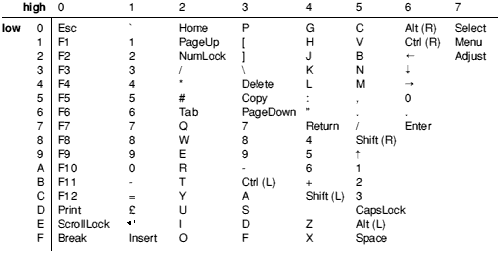
Low-level internal key numbers
Where there is some ambiguity, eg the digit keys, it should be clear from referring to the keyboard layout which code refers to which key. The keys are numbered top to bottom, left to right, starting from Esc at the top left corner. 4D is unused on the UK model, but may be used on some other models for an extra key.
Note that the keycodes given in this event bear no relationship to any other code you will see. They are not, for example, related to the INKEY numbers described in the chapter entitled Character Input. They apply to the keyboard supplied on the UK model.
R0 = 12
R1 = 2
R2 = 0
This event is generated whenever the sound beat counter is reset to zero, marking the start of a bar. See the chapter entitled The Sound system for more details.
The 0 in R2 may change in future versions to give the invocation number of the task causing the event.
R0 = 13
This event is claimed by the PC Emulator package.
R0 = 14
R1 = receive handle
R2 = status of completed operation
This event is generated when an Econet reception completes. The status returned in R2 will always be 9 (Status_Received). See the chapter entitled Econet for further details.
R0 = 15
R1 = transmit handle
R2 = status of completed operation
This event is generated when an Econet transmission completes. The status returned in R2 can have the following values:
| 0 | Transmitted |
| 1 | Line jammed |
| 2 | Net error |
| 3 | Not listening |
| 4 | No clock |
See the chapter entitled Econet for further details.
R0 = 16
R1 = pointer to argument buffer
R2 = remote procedure call number
R3 = station number
R4 = network number
This event is generated when an Econet operating system remote procedure call occurs. Current remote procedure call numbers are:
| 0 | Character from Notify |
| 1 | Initialise Remote |
| 2 | Get View parameters |
| 3 | Cause fatal error |
| 4 | Character from Remote |
See the chapter entitled Econet for further details.
R0 = 17
R1 = event code
This event is generated when certain MIDI events occur. The values R1 may have are:
| 0 | A byte has been received when the buffer was previously empty |
| 1 | A MIDI error occurred in the background |
| 2 | The scheduler queue is about to empty, and you can schedule more data. |
These events only occur if you have fitted an expansion card with MIDI sockets. See the manual supplied with the card for further details.
R0 = 19
R1 = event code
R2 = socket descriptor
This event is generated when certain Internet events occur. The values R1 may have are:
| 0 | A socket has input waiting to be read |
| 1 | An urgent event has occurred, such as the arrival of out-of-band data |
| 2 | A socket connection is broken. |
These events only occur if you are using the Internet module supplied with the TCP/IP Protocol Suite. See the TCP/IP Programmer's Guide for further details.
R0 = 22
R1 = device driver's handle
R2 = file handle
R3 = 0
This event is generated when the SWI DeviceFS_ReceivedCharacter is called on an unbuffered stream, and the previously received character has not been read. The new character overwrites any previous character.
R0 = 24
R1 = pointer to data buffer chain containing Rx data
R2 = pointer to name of interface controlled by driver ('et', 'en', etc)
R3 = physical unit number (0 - 3)
R4 = Rx frame type
This event is generated by a driver to indicate to the Internet module that it has received and stored a frame from the network.
This event is not used by DCI4 versions of the Internet module, such as the one in RISC OS 3.6.
R0 = 25
R1 = pointer to data buffer chain containing Tx data
R2 = pointer to name of interface controlled by driver ('et', 'en', etc)
R3 = physical unit number (0 - 3)
R4 = error number (driver specific), or 0 if successful
This event is generated by a driver to indicate to the Internet module that it has completed a transmission request. It does not necessarily imply successful transmission and reception by the target host.
This event is not used by DCI4 versions of the Internet module, such as the one in RISC OS 3.6.
R0 = 28
R1 = status bits for BMU variable 10 (see Variable Read/Write Description)
This event is generated by the Portable module when it receives interrupts from the BMU (battery management unit). You must not claim it yourself. See the chapter entitled The Portable module for further details.