
|
www.riscos.com Technical Support: |
An interrupt is a signal sent to the ARM processor from a hardware device, indicating that the device requires attention. One is sent, for example, when a key has been pressed or when one of the software timers needs updating. This sending of a signal is known as an interrupt request.
RISC OS deals with the interrupt by temporarily halting its current task, and entering an interrupt routine. This routine deals with the interrupting device very quickly - so quickly, in fact, that you will never realise that your program has been interrupted.
Interrupts provide a very efficient means of control since the processor doesn't have to be responsible for regularly checking to see if any hardware devices need attention. Instead, it can concentrate on executing your code or whatever else its current main task may be, and only deal with hardware devices when necessary.
Amongst the devices which are handled under interrupts on RISC OS computers are the:
Additionally, external hardware such as expansion cards may cause new interrupts to be generated. For example, the analogue to digital convertor on the BBC I/O expansion card can interrupt when it has finished a conversion. It is therefore possible to install routines which deal with these new interrupts.
Each potential source of interrupts has a device number. There are corresponding device vectors; installed on each vector there is a default device driver that receives only the interrupts from that device.
Unless you are adding your own interrupt-generating devices to the computer, you should not need to alter the interrupt system.
The device numbers correspond directly to bits of the interrupt registers held in the IOC chip:
| Device number | Corresponds to: |
|---|---|
| 0 | Bit 0 of IRQ A registers |
| 1 | Bit 1 of IRQ A registers |
| ... | |
| 7 | Bit 7 of IRQ A registers |
| 8 | Bit 0 of IRQ B registers |
| 9 | Bit 1 of IRQ B registers |
| ... | |
| 15 | Bit 7 of IRQ B registers |
See the chapter entitled IOC registers for more details.
Not all RISC OS computers use the same interrupt generating hardware. Early models (eg the Archimedes 300, 400 and 500 series, and the A3000) use a variety of peripheral control chips; current models (eg the A5000) use the 82C710 or 82C711 chip; future models may use other peripheral controllers. These different peripheral controllers are mapped differently onto the IOC chip's IRQ registers. Consequently, device numbers differ between models of RISC OS computers.
You can distinguish between the different peripheral controllers and their properties by calling OS_ReadSysInfo using its various reason codes.
For early models (ie the Archimedes 300, 400 and 500 series, and the A3000), the device numbers are:
| 0 | Printer Busy |
| 1 | Serial port Ringing Indicator |
| 2 | Printer Acknowledge |
| 3 | VSync Pulse |
| 4 | Power on reset - this should never appear in normal use |
| 5 | IOC Timer 0 |
| 6 | IOC Timer 1 |
| 7 | FIQ Downgrade - reserved for the use of the current owner of FIQ |
| 8 | Expansion card FIQ Downgrade - this should normally be masked off |
| 9 | Sound system buffer change |
| 10 | Serial port controller interrupt |
| 11 | Hard disc controller interrupt |
| 12 | Floppy disc changed |
| 13 | Expansion card interrupt |
| 14 | Keyboard serial transmit register empty |
| 15 | Keyboard serial receive register full |
For models using the 82C710 or 82C711 peripheral controller (eg the A5000), the device numbers are:
| 0 | Printer interrupt from 82C710/711 |
| 1 | Low battery warning |
| 2 | Floppy disc Index |
| 3 | VSync Pulse |
| 4 | Power on reset - this should never appear in normal use |
| 5 | IOC Timer 0 |
| 6 | IOC Timer 1 |
| 7 | FIQ Downgrade - reserved for the use of the current owner of FIQ |
| 8 | Expansion card FIQ Downgrade - this should normally be masked off |
| 9 | Sound system buffer change |
| 10 | Serial port interrupt from 82C710/711 - also mapped to FIQ device 4 |
| 11 | Floppy disc interrupt from 82C710/711 |
| 12 | IDE hard disc interrupt |
| 13 | Expansion card interrupt |
| 14 | Keyboard serial transmit register empty |
| 15 | Keyboard serial receive register full |
(Device numbers 3 - 9 and 13 - 15 have the same meaning as for early models.)
Note that RISC OS 2 does not support the 82C710 or 82C711 peripheral controller.
Just like other vectors in RISC OS, you can claim the device vectors and get them to call a different routine. You do this using the SWI OS_ClaimDeviceVector.
Most of the device vectors only call the most recent routine that claimed the vector. There is no mechanism to pass on the call to earlier claimants, as it is not sensible to have many routines handling one device. However, old claimants remain on the vector, and if you release the vector using OS_ReleaseDeviceVector, the previous owner of the vector is re-installed.
The exceptions to this are device vectors 8 and 13, which handle FIQs and IRQs (respectively) which are generated by expansion cards. These can have many routines installed on them, as it is possible to add many expansion cards to the computer. Each claimant specifies exactly which interrupts it is interested in; RISC OS then ensures that only the correct routine is called.
Note that when you claim a device vector, RISC OS will automatically remove from the chain any earlier instances of the exact same routine (ie one that uses the same code and workspace).
If you release a device vector, and there are no earlier claimants of that vector, RISC OS will automatically disable interrupts from the corresponding device. You must not attempt to disable the interrupts yourself. There is thus guaranteed to be a device driver for each device number that can generate interrupts.
After the release of RISC OS 2, a module called IRQUtils was released to improve interrupt latency.
The changes this made have now been incorporated in RISC OS 's kernel. A dummy module named IRQUtils has been included with an appropriate version number, so that applications written to run under RISC OS 2 that check for its presence will still run correctly.
R0 = device number
R1 = address of device driver routine
R2 = value to be passed in R12 when device driver is called
R3 = address of interrupt status, if R0 = 8 or 13 on entry (ie an expansion card)
R4 = interrupt mask to use, if R0 = 8 or 13 on entry (ie an expansion card)
R0 - R4 preserved
Interrupts are disabled
Fast interrupts are enabled
Processor is in SVC mode
SWI is not re-entrant
This call installs the device driver, the address of which is given in R1, on the device vector given in R0. If the same driver has already been installed on the vector (ie the same parameters were used to install a driver) then the old copy is removed from the vector. Note that this call does not enable interrupts from the device (cf OS_ReleaseDeviceVector).
The previous driver is added to the list of earlier claimants.
If R0 = 8 or 13 then the device driver routine is for an expansion card. R3 gives the address where the expansion card's interrupt status is mapped into memory - see Interrupt Status Pointers onwards of the chapter Expansion Cards and Extension ROMs. Your device driver is called if the IOC chip receives an interrupt from an expansion card, and ( LDRB [R3] AND R4 ) is non-zero.
For all other values of R0, your driver is called if the IOC chip receives an interrupt from the appropriate device, the corresponding IOC interrupt mask bit is set, and your driver was the last to claim the vector.
R0 = device number
R1 = address of device driver routine
R2 = R12 value
R3 = interrupt location if R0 = 8 or 13 on entry (ie an expansion card)
R4 = interrupt mask if R0 = 8 or 13 on entry (ie an expansion card)
R0 - R4 preserved
Interrupts are disabled
Fast interrupts are enabled
Processor is in SVC mode
SWI is not re-entrant
This call removes a driver from the list of claimants of a device vector. The device driver is identified by the contents of the registers on entry; R0 - R2 (R0 - R4 if R0 = 8 or 13) must be the same as when the device driver was installed on the vector.
The previous owner of the vector is re-installed at the head of the chain. If there is no previous owner, then IRQs from the corresponding device are disabled.
You must not attempt to disable a device's IRQs within IOC when you release its vector. For expansion card IRQs (ie R0 = 8 or 13 on entry), you should prevent your device from interrupting again by programming the hardware on your expansion card.
This section gives you more technical details of how the RISC OS interrupt system works. You should refer to it if:
Interrupts are generated and the device driving routine called as follows:
If the device was an expansion card, RISC OS checks each routine on the expansion card device vector, starting with the most recent claimant. The contents of the interrupt status byte are ANDed with the mask (as passed in R3 and R4 when the routine was installed). If the result is non-zero, the routine is called; otherwise the next most recent claimant is checked.
Whatever the device number, if no routine is found to handle the interrupt then IrqV (the unknown IRQ vector) is called. By default this disables the interrupting device by clearing the corresponding bit of its interrupt mask - but the call may be intercepted by routines written to work under the old Arthur operating system.
The addresses of the IOC registers are given in the IOC registers.
When a routine that has claimed a device vector is called:
Your routine must:
In doing so, you may corrupt registers R0 - R3 and R12.
There are more restrictions on writing code to run under IRQ mode than there are under SVC mode. These apply to:
Interrupt handling routines must be quick to execute. This is because they are entered with interrupts disabled, so while they are running other hardware may be kept waiting. This slows the machine down considerably.
In practice, 100![[MU]](../symbols/entities/956.png) s is the longest you should leave interrupts disabled. If your routine will take longer than this, try to make it shorter. If all else fails, your routine must re-enable interrupts. It should do so by clearing the I bit of R15, using for example:
s is the longest you should leave interrupts disabled. If your routine will take longer than this, try to make it shorter. If all else fails, your routine must re-enable interrupts. It should do so by clearing the I bit of R15, using for example:
        MOV     Rtemp, PC    ; I_Bit set in PSR
        TEQP    Rtemp,#I_bit ; Note TEQ is like EOR: so clears I_Bit in PSR
where I_bit is a constant having only the I bit set. You cannot simply do TEQP PC,#I_bit, because in this instruction the PC is presented without the PSR bits. For more details see Appendix A: ARM assembler.
If your routine does re-enable interrupts, it must be able to cope if a second interrupt occurs, and hence the routine being entered for a second time (ie re-entrancy occurring).
Calling SWIs from device driver routines is quite similar to calling them from SWI routines. Again the problem is that R14_svc (the return address for SWIs) may get corrupted. For example:
The solution used with device driver routines is the same as that for SWI routines. R14_svc is pushed on the stack before the SWI is called, and pulled afterwards. However, this is more complex as you have to first change from IRQ to SVC mode. A recommended way of doing so is:
        MOV     R9, PC                  ; Save current status/mode
        ORR     R8, R9, #SVC_Mode       ; Derive SVC-mode version of it
        TEQP    R8, #0                  ; Enter SVC mode
        MOV     R0, R0                  ; No-op to prevent contention
        STMFD   R13!, {R14}             ; Save R14_SVC
        SWI     XXXX                    ; Do the SWI
        LDMFD   R13!, {R14}             ; Restore R14_SVC
        TEQP    R9, #0                  ; Re-enter original processor mode
        MOV     R0, R0                  ; No-op to prevent contention
SVC_Mode is 3. Of course, you must preserve R8 and R9 as well, using the full descending IRQ stack. If you want to check flags on exit from the SWI (eg the V flag), you must do so before you re-enter the original processor mode, as this method restores not just the mode bits, but also all the original flags.
An alternative method is shown below. It is one instruction longer, but only uses one temporary register (R8), and allows testing the flags returned by the SWI after restoring the original mode:
        MOV     R8, PC                  ; R8 holds PC and PSR
        AND     R8, R8, #3              ; Extract current mode bits
        EOR     R8, R8, #SVC_Mode       ; R8 = current mode EOR SVC_Mode
        TEQP    R8, PC                  ; Enter SVC mode
        MOV     R0, R0                  ; No-op to prevent contention
        STMFD   R13!, {R14}             ; Save R14_SVC
        SWI     XXXX                    ; Do the SWI
        LDMFD   R13!, {R14}             ; Restore R14_SVC
        TEQP    R8, PC                  ; Restore mode, preserving other flags
        MOV     R0, R0                  ; No-op to prevent contention
Interrupt handling routines must only call error-returning SWIs ('X' SWIs). If you do get an error returned to the routine, you cannot return that error elsewhere. Instead you must take appropriate action within the routine. You may also like to store an error indication, so that the next call to a SWI in the module that provides the routine (or the current call, if already threaded) will generate an error.
There are some SWIs you shouldn't call at all from an interrupt handling routine, even with the above precautions. This is because they are not re-entrant; that is, they can't be entered while an earlier call to them may still be in progress. One common reason for this is if the routine uses some private workspace. For example:
The documentation of each SWI clearly states if it is re-entrant - ie if you can call it from an interrupt handling routine. There are three common entries:
In general, OS_Byte and OS_Word calls can be used. OS_WriteC and routines which use it should never be called.
Before your routine returns, it must service the interrupt - that is, give the device the attention it needs, which originally caused it to generate the interrupt. You must then clear the interrupt condition, to stop the device carrying on generating the same interrupt. How you do this depends on the device, but will usually involve accessing the hardware that is generating the interrupt. See the relevant hardware data sheets for information.
There are actually two classes of interrupt requests. So far we have been looking at the normal interrupt request, or IRQ. The second type is a fast interrupt request, or FIQ. Fast interrupts are generated by devices which demand that their request is dealt with as quickly as possible. They are dealt with at a higher priority than interrupts (ie normal IRQs).
Fast interrupts are a separate system. There are separate registers in the IOC chip, separate inputs to the chip, and a separate connection to the ARM. The ARM has a processor mode reserved for FIQs, and a hardware vector.
Devices handled under FIQs also have device numbers. Again, the device numbers correspond to the bits in IOC registers: these are the FIQ interrupt registers.
| Device number | Corresponds to: |
|---|---|
| 0 | Bit 0 of FIQ registers |
| 1 | Bit1 of FIQ registers |
| ... | |
| 7 | Bit 7 of FIQ registers |
Just like IRQ device numbers, FIQ device numbers differ between models of RISC OS computers, depending on the peripheral controller chips used. For early models (eg the Archimedes 300, 400 and 500 series, and the A3000), the FIQ device numbers are:
| 0 | Floppy disc data request |
| 1 | Floppy disc controller interrupt |
| 2 | Econet interrupt |
| 3 | C3 pin on IOC |
| 4 | C4 pin on IOC |
| 5 | C5 pin on IOC |
| 6 | Expansion card interrupt |
| 7 | Force FIQ - this bit is always set, but usually masked out |
| 0 | Floppy DMA data request |
| 1 | FH1 pin on IOC |
| 2 | Econet interrupt |
| 3 | C3 pin on IOC |
| 4 | Serial port interrupt from 82C710/711 - also mapped to IRQ device 10 |
| 5 | C5 pin on IOC |
| 6 | Expansion card interrupt |
| 7 | Force FIQ - this bit is always set, but usually masked out |
(FIQ device numbers 2, 3 and 5 - 7 have the same meaning as for early models.)
Again we make the point that RISC OS 2 does not support the 82C710 or 82C711 peripheral controller.
In many ways FIQs are similar to IRQs. So FIQ routines must:
There are three important differences:
When a FIQ is generated execution passes directly to code at the FIQ hardware vector. By default, the code that is installed here handles FIQs generated by the Econet module, if it is present. The Econet module is the default owner of the FIQ vector.
When other parts of RISC OS want to use FIQs, for example to perform a disc transfer under interrupts, they claim the vector, replace the default code, and then release the vector. RISC OS automatically re-installs the default code.
Obviously only one current FIQ owner is supported.
It is vital that you only claim the FIQ vector for the absolute minimum time necessary. For example, ADFS uses FIQs to perform disc transfers; but it releases the FIQ vector between each sector.
You must follow a similar procedure if you want to use FIQs. This is the sequence you must follow:
To claim from the background, the reason code in R1 must be &47 (Claim FIQ in background). This service call may fail, but this failure does not imply an error - merely that FIQs could not be claimed. You must leave your routine to allow the foreground routine to finish using FIQs and release them. You should schedule a later retry; for example with a disc, you would retry next revolution of the disc. If R1 = 0 on return, you successfully claimed the FIQ vector.
You may need to know in more detail how fast interrupts are generated and the FIQ hardware vector is called:
The addresses of the IOC registers are given at the end of the chapter.
There will be times when you want to disable interrupts (ie IRQs). You must only do so with great care; and particularly not for long periods of time since this will have various unwanted effects such as stopping the clock, disabling the keyboard, etc.
The easiest way to disable and re-enable interrupts from user mode is to use the SWIs provided. These are OS_IntOff and OS_IntOn. They have no entry or exit conditions, and are described in full below.
To disable specific devices, or fast interrupts, you need to be in a privileged mode. The example below shows you how to use the SWI OS_EnterOS to enter SVC mode. This is described in more detail below.
Normally you won't need to do this, because RISC OS places you in a privileged mode during module initialisation, service and finalisation entries -the times you are most likely to want to disable devices, or fast interrupts.
Once you are in a privileged mode, you can disable interrupts by setting the I bit in R15. You can also disable fast interrupts by setting the F bit.
To disable specific devices you must first have disabled all interrupts. You then clear the relevant bits in any of the IOC's interrupt mask registers. This must be done in very few (no more than five) instructions. Finally, you must re-enable interrupts:
MOV     R2,#IOC                 ; Point R2 at IOC before disabling interrupts
SWI     "OS_EnterOS"            ; Enter SVC mode
MOV     R0,PC                   ; Get status in R0
ORR     R1,R0,#&0C000000        ; Set the interrupt masks
TEQP    R1,#0                   ; Update PSR
...                             ; Write to IOC here in < 5 instructions, eg:
LDRB    R1,[R2,#IOCIRQMskA]
ORR     R1,R1,#Timer1Bit        ; Enable Timer1
                                ; If BIC is used instead of ORR, Timer1 is disabled
STRB    R1,[R2,#IOCIRQMskA]
...                             ; End of write to IOC
TEQP    R0,#3                   ; Restore entry state and return to user mode
MOV     R0,R0                   ; NOP to avoid contention
FIQs must be disabled because the mask has FIQ downgrade bits. If the current FIQ owning process alters these bits between your reading the mask and writing it, the process will not then get the IRQ that it just requested the FIQ be downgraded to.
R1 = &0B (reason code)
R1 = 0 to claim, else preserved to pass on
This service call must be issued by any module immediately after it releases the FIQ hardware vector. You may claim this service call if you wish to usurp the default FIQ owner (the Econet module) and install your own code on the FIQ hardware vector.
If no module claims this service call, then Econet does so, and installs its own code on the FIQ hardware vector. Should even Econet not claim the service call - for example if the Econet module has been unplugged - then the kernel installs its default FIQ handler.
See the chapter entitled Using FIQs for details of other steps to take when claiming or releasing the FIQ hardware vector, and also the chapter entitled Hardware vectors for additional information about the vector.
R1 = &0C (reason code)
R1 = 0 to claim, else preserved to pass on
This service call must be issued by any module running as a foreground task (ie not as an IRQ process) that wishes to claim the FIQ hardware vector.
It informs the current FIQ owner that it must release the vector as soon as it can cleanly do so. The current owner must complete without disruption any unfinished FIQ processing, release the vector, and then claim the service call by setting R1 to zero. As soon as the claimant finds that the service call has been claimed, it knows it has claimed the FIQ hardware vector.
See the chapter entitled Using FIQs for details of other steps to take when claiming or releasing the FIQ hardware vector, and also the chapter entitled Hardware vectors for additional information about the vector.
R1 = &47 (reason code)
R1 = 0 to claim, else preserved to pass on
This service call must be issued by any module running as a background task (ie as an IRQ process) that wishes to claim the FIQ hardware vector. It may also be issued by foreground tasks that wish to poll the FIQ vector for availability. Unlike Service_ClaimFIQ, this call may return with R1 preserved (ie not claimed), meaning that the current FIQ owner has not released the vector.
The service call informs the current FIQ owner that it must release the vector if it can immediately do so. If the current owner is busy with a FIQ, it must take no action, merely passing on the service call; if however it is idle, it may release the vector and then claim the service call by setting R1 to zero. If the claimant finds that the service call has been claimed, it knows it has successfully claimed the FIQ hardware vector; however, if the claimant finds that the service call has not been claimed, it knows the current owner has not released the FIQ hardware vector, in which case the claimant may reissue the service call at a later time.
Background claims are released by Service_ReleaseFIQ, as before.
See the chapter entitled Using FIQs for details of other steps to take when claiming or releasing the FIQ hardware vector, and also the chapter entitled Hardware vectors for additional information about the vector.
No parameters passed in registers
Registers preserved
Interrupt status is undefined on entry
Interrupts are enabled on exit
Fast interrupt status is unaltered
Processor is in SVC mode
SWI is re-entrant
This call enables interrupts and returns to the caller with the processor mode unchanged.
None
Disables interrupts
No parameters passed in registers
Registers preserved
Interrupt status is undefined on entry
Interrupts are disabled on exit
Fast interrupt status is unaltered
Processor is in SVC mode
SWI is re-entrant
This call disables interrupts and returns to the caller with the processor mode unchanged.
None
Sets the processor to SVC mode
No parameters passed in registers
Registers preserved
Interrupt status is unaltered
Fast interrupt status is unaltered
Processor is in SVC mode during the routine, and on exit
SWI is re-entrant
This call returns to the caller in SVC mode. This leaves you using the SVC stack. The interrupt states remain unchanged.
None
It will help you to use interrupts to their full potential if you have a good knowledge of the hardware used to build the computer. We don't have the space to give you full details of every RISC OS computer built by Acorn in this manual.
Below we tell you where the IOC chip and some of the various peripheral controllers of a RISC OS computer are mapped into memory on an Archimedes computer. Although these may be taken as typical of RISC OS computers, there is no guarantee that other computers will be similarly mapped. Indeed, even the details below are subject to change; the peripheral controllers may be changed as improved ones become available, or the mapping may be redefined.
Always use defined software interfaces in preference to directly accessing the hardware.
If you need to know more, you can:
The IOC registers are a single byte wide, and are mapped into memory like this:
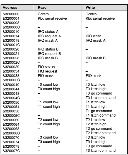
Typical memory mapping of IOC registers
The IOC chip's control register allows you to read and write its six external control pins C0 - C6, and to read two other pins. Again there are differences between models of RISC OS computers, depending on the peripheral controllers used. For early models (eg the Archimedes 300, 400 and 500 series, and the A3000), the bits of the control register are mapped as follows:
| Bit | Function |
|---|---|
| 0 | IIC serial bus data |
| 1 | IIC serial bus clock |
| 2 | Floppy disc ready |
| 3 | Reset enable (A540/R200 series only) |
| 4 | Current level of C4 pin on IOC (available on Auxiliary I/O connector) |
| 5 | Speaker mute |
| 6 | Current level of -IF pin on IOC (Printer Acknowledge signal) |
| 7 | Current level of IR pin on IOC (Vertical Flyback signal) |
For models using the 82C710 or 82C711 peripheral controller (eg the A5000), the bits of the control register are mapped as follows:
| Bit | Function |
|---|---|
| 0 | IIC serial bus data |
| 1 | IIC serial bus clock |
| 2 | Floppy disc density |
| 3 | Unique machine ID chip - control pin |
| 4 | Serial FIQ |
| 5 | Speaker mute |
| 6 | Current level of -IF pin on IOC (Floppy disc Index signal) |
| 7 | Current level of IR pin on IOC (Vertical Flyback signal) |
Again we make the point that RISC OS 2 does not support the 82C710 or 82C711 peripheral controller.
Other devices and peripheral controllers are mapped into memory in these locations on early model RISC OS computers (eg the Archimedes 300, 400 and 500 series, and the A3000):
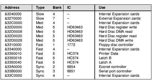
Early memory mapping of non-IOC devices and peripheral controllers
Current models that use the 82C710 or 82C711 (eg the A5000) use this mapping:
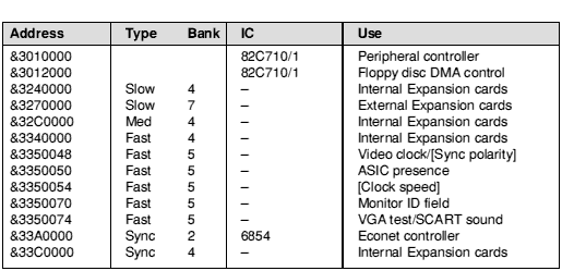
Typical memory mapping of non-IOC devices and peripheral controllers